 |
924Board.org
Discussion Forum of 924.org
|
| View previous topic :: View next topic |
| Author |
Message |
jacobroufa

Joined: 18 Nov 2016
Posts: 531
Location: Belvidere, IL
|
 Posted: Wed Jun 01, 2022 7:08 am Post subject: Posted: Wed Jun 01, 2022 7:08 am Post subject: |
 |
|
https://www.youtube.com/watch?v=C4IDlKqYhqs

I realized only after I was editing the video that the position of the camera was really too low to see anything out of the window. I think it is decent for sound however. I will work on using a different setup to have a camera view of the drive, and next time no windows open at all... The wind noise is simply too much.
_________________
1980 Porsche 931
1981 Porsche 924 Weissach |
|
| Back to top |
|
 |
jacobroufa
Joined: 18 Nov 2016
Posts: 531
Location: Belvidere, IL
|
| Posted: Wed Jun 01, 2022 7:16 am Post subject: |
|
|
I should emphasize, this used to be fairly decent around town due to good momentum, but 45-55 felt most comfortable and acceptable. 65mph feels no problem anymore with this setup, even faster is tolerable, to the point where I feel like among my next upgrades I must to add a rear sway bar (already planned, have most of the parts) and bigger diameter / wider tires for more grip.
Anyone in the Chicago area got a 5 lug swap available? 
_________________
1980 Porsche 931
1981 Porsche 924 Weissach |
|
| Back to top |
|
|
931-1979
Joined: 13 May 2016
Posts: 5
Location: Austria
|
| Posted: Wed Jun 01, 2022 8:12 pm Post subject: |
|
|
I was lucky and had the opportunity to visit Ciprian and test the 924SC. The car drives great with the Supercharger! Thanks again for the exciting day! David
_________________
931/1 - 1979
924 2,0 - 1982 |
|
| Back to top |
|
|
morghen

Joined: 21 Jan 2005
Posts: 8889
Location: Romania
|
| Posted: Thu Jun 02, 2022 7:47 am Post subject: |
|
|
Hey David, thanks for visiting and for the kind words.
_________________
https://www.the924.com |
|
| Back to top |
|
|
jacobroufa
Joined: 18 Nov 2016
Posts: 531
Location: Belvidere, IL
|
| Posted: Mon Jun 06, 2022 11:59 am Post subject: |
|
|
Made some good progress on the MicroSquirt today as it was the first day I started on it.
AC hoses are out of the cabin. I removed the top hose entirely and the bottom hose just cut on the footwell side of the firewall..
Ran the MS wiring loom through that top hole along with a fresh power wire and the O2 loom.
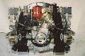
Engine bay so far (pre-connector soldering). Took this to ask Eddie what he did with the remaining loom. I will take a note from him and bundle it up near my brake booster.
https://imgur.com/l20MJLm
Got the MAP sensor and frequency valve connectors soldered and heat shrunk. Unsure where I will place the MAP sensor -- it'll probably get zip tied to an existing fixture.
I pulled the wires back into the cabin that I will need.. Switched power, O2 (will connect with the back of the Innovate AFR), fuel pump, tach.
https://imgur.com/Qw8Y4VL
Ignore the tach green/yellow in the video -- I had to pull a different wire back through -- I accidentally grabbed the tach OUT not the VR+ wire that is required...
Also shown very briefly in that second video is the back of the passenger kick panel where I secured the MS box, two relays (one main relay powering the AFR and fuel pump relay, second for the fuel pump) and a fuse block.
---
So tomorrow I plan to finish soldering the spade connectors for the interior wiring, and hopefully figure out the tach signal and fuel pump. I also need to run to the store to get a bigger ring terminal to ground the MS in the engine bay, and more 1/4" heat shrink tubing.
_________________
1980 Porsche 931
1981 Porsche 924 Weissach |
|
| Back to top |
|
|
jacobroufa
Joined: 18 Nov 2016
Posts: 531
Location: Belvidere, IL
|
| Posted: Mon Jun 06, 2022 12:02 pm Post subject: |
|
|
And of course as I posted just now I realized I made a bonehead maneuver and did not wire the frequency valve properly.... 

I ran INJ2 to it, and a Sensor Ground... Not the switched 12v.. I will have to correct that tomorrow as well I guess and run another wire through the bulkhead..
I know it shows in this image but I will not be running INJ1, only controlling the frequency valve here. If I ever get the FrankenCIS WUR block that will be INJ1 controlled but for now I'll set that map to be 100% duty cycle throughout.
_________________
1980 Porsche 931
1981 Porsche 924 Weissach |
|
| Back to top |
|
|
morghen
Joined: 21 Jan 2005
Posts: 8889
Location: Romania
|
| Posted: Mon Jun 06, 2022 6:32 pm Post subject: |
|
|
Oh wow, this should be good!
I didnt have time to play with UTCIS anymore as i had to finish producing and ship the last batch of kits and this week the 924 goes for a new exhaust.
_________________
https://www.the924.com |
|
| Back to top |
|
|
Fasteddie313

Joined: 29 Sep 2013
Posts: 2596
Location: MI
|
| Posted: Mon Jun 06, 2022 9:50 pm Post subject: |
|
|
The 5v voltage wire and the common sensor ground wire you are about to wire to the map sensor, these wires are shared with many other sensors as commons, so keep in mind that in the future you may be tapping into them to feed to more sensors in the future if you so choose..
| jacobroufa wrote: | | If I ever get the FrankenCIS WUR block that will be INJ1 controlled but for now I'll set that map to be 100% duty cycle throughout. |
Just a small correction..
The maps will be scaled 0-200 for 0-100% duty cycle, so a change of 1 on the map to s a change of 0.5% duty cycle, for finer control/greater resolution..
So when you set the map to “100”, that is actually 50% duty cycle..
Set VE map 1 (WUR) to all 100s and forget about it as you won’t be controlling a WUR..
Set VE map 2 to all 100s and that should run your frequency valve at 50% duty cycle throughout and run exactly the same as it has been stock with your O2 sensor unplugged (besides whatever the WOT switch does to duty cycle on an NA, if anything, I forget)..
Then set your AFR screw on your distributor to idle at 14.7 after you are good and warmed up, and adjust the rest of your running range from there..
If you possibly find yourself needing numbers higher than say 160 in your map to get as rich as you want, you could set your AFR screw to bias rich and use your map to lean out idle..
You could set your VE2 map to all 80s in the map, for 40% duty cycle, and then use your AFR screw to set your idle to 14.7 with the map at 80, so then you will have all the way from 80-200 to increase richness from your base tune instead of from 100-200, to give you more range on that side..
Probably not necessary though..
_________________
80 Turbo - Slightly Modified |
|
| Back to top |
|
|
jacobroufa
Joined: 18 Nov 2016
Posts: 531
Location: Belvidere, IL
|
| Posted: Thu Jun 09, 2022 1:11 am Post subject: |
|
|
Definitely, understand re: the common wiring...
Thanks for the correction on the maps -- my understanding is still growing with this.
---
Just wanted to update to say that it's been raining the last several days and the car's been outside instead of in the garage so it's unlikely to be moved at least until later today when it dries up.. Also I've had a minor surgery so feeling rather rough today. But I have the rest of the week off and still hope to spend some small amount of time with wiring to meet my goal. We will see how successful that is.
Mike pointed out to me that the tach signal can be taken from coil negative so I should not have to pull the VR+ into the cabin or tear into the gauge cluster to get that.. I will see how that works first before digging for the signal behind the actual tachometer.
_________________
1980 Porsche 931
1981 Porsche 924 Weissach |
|
| Back to top |
|
|
Fasteddie313
Joined: 29 Sep 2013
Posts: 2596
Location: MI
|
| Posted: Thu Jun 09, 2022 6:08 am Post subject: |
|
|
I believe that is correct
_________________
80 Turbo - Slightly Modified |
|
| Back to top |
|
|
Fifty50Plus
Joined: 28 Feb 2008
Posts: 1362
Location: Washington DC area
|
| Posted: Thu Jun 09, 2022 6:41 am Post subject: |
|
|
Old Porsches have their electronic tach lead connected directly to the negative side of the coil.
_________________
1979 924 NA race car
1982 924 NA race car - Sold
1982 924 Turbo almost a PoS
1981 924 Turbo a real PoS, new engine
1982 924 Turbo nice body, blown engine
1972 911 E race car - going to Vintage
Various 944s to become IT-S race car |
|
| Back to top |
|
|
jacobroufa
Joined: 18 Nov 2016
Posts: 531
Location: Belvidere, IL
|
| Posted: Fri Jul 01, 2022 11:23 pm Post subject: |
|
|
Making progress on this again finally, after a long June of not feeling up to doing anything at all.
So I got the engine bay side of things cleaned up and nearly ready to go yesterday:
* I ran a fresh fused 12v lead to the injector instead of the ground I had soldered mistakenly to the one side.
* Terminated the ground leads and grounded them on the battery post. Probably I could ground them closer to the rest of the harness like on the AAV but I do not relish tearing apart my intake tract any more than I have to!
* Secured the MAP sensor next to the coil.
* Ran VE1+ to coil negative -- I had a 2-tab fitting on the negative side that I swapped with the 3-tab from the positive side of the coil.
* Coiled up the remaining wires in the loom and tucked them away next to the coil.

Left to do in the engine bay:
* Route vacuum to the MAP sensor. I will probably reinstall the factory brass Y junction off the back of the intake for this.
* Remove the intake boot in order to unplug factory frequency valve connection and plug in MS injector harness.
----
And on the inside I have gotten some progress yesterday as well!

Still todo inside:
* Buy more blade fuses..
* Finish running injector 12v wire to the fuse panel
* Make a multi-tap off of one relay to power multiple fuses -- essentially we have two relays here and one will power the MS alone for isolation/protection and the other will power the rest of the circuits we are adding
* Find the fuel pump lead on the stock fuse panel and connect it to the new fuse panel.
Other than that I think it's only software that's left.
So I did have one question after doing the majority of the remaining wiring. And this is kind of generic but I don't have the best understanding of relay circuits.. The main relay (powering only MS computer) is grounded on one terminal. The secondary relay instead of grounding to the chassis is taking the "Fuel Pump" signal wire from the MS. What is the purpose of this in the circuit? Does it control the ability of that relay to properly conduct current due to the ground? I thought that terminal had to be grounded because we have switched power on one side and then our power through circuit on the other.. but that is not a grounding circuit coming from MS, it is power..
_________________
1980 Porsche 931
1981 Porsche 924 Weissach |
|
| Back to top |
|
|
Fasteddie313
Joined: 29 Sep 2013
Posts: 2596
Location: MI
|
| Posted: Fri Jul 01, 2022 11:36 pm Post subject: |
|
|
The purpose of the 2 relays..
1 comes in with your key ignition, it turns the microsquirt controller on (and use it for whatever else you want, good ignition switched power source)
2, the “fuel pump” relay’s purpose is the same as the safety fuel cuts in the original 924/931 fuel pump relays..
To only run the fuel pump when it’s needed, and to stop it if their is a problem..
This will prime with ignition on, and pump when it sees a tach signal..
Basically the same as the 931 relay, it cuts fuel if it doesn't see a tach signal..
But, the signal coming from the MS box for this is switched GROUND, instead of switched power, and you have your ignition relay feed the power to it..
So this relay will not have power unless your key is on, and will not have ground unless the MS sees tach or is priming..
_________________
80 Turbo - Slightly Modified |
|
| Back to top |
|
|
jacobroufa
Joined: 18 Nov 2016
Posts: 531
Location: Belvidere, IL
|
| Posted: Fri Jul 01, 2022 11:48 pm Post subject: |
|
|
OK cool. Thanks for the run down Eddie! I saw the amp rating on the fuel pump wire from MS and thought that it was switched power due to that not switched ground. Appreciate the clarification!
So it works roughly as I thought it would, but given this I don't fully understand the MS wiring diagram -- don't think it'll work fully for me -- because it has the WBO2 on the fuel pump relay side. I want to make sure that it is powered from the main relay then I suppose, since it is an independent system.
So I guess I will have two "main" circuits here then: MS, AFR/WBO2
And two "fuel pump" circuits: fuel pump, 12v to injector (frequency valve)
And I will correct my wiring here again, as I've got a switched ignition 12v source currently wired as the trigger for both relays instead of using "main" relay power to trigger "fuel pump" relay.
_________________
1980 Porsche 931
1981 Porsche 924 Weissach |
|
| Back to top |
|
|
Fasteddie313
Joined: 29 Sep 2013
Posts: 2596
Location: MI
|
| Posted: Sat Jul 02, 2022 12:31 am Post subject: |
|
|
| jacobroufa wrote: |
And I will correct my wiring here again, as I've got a switched ignition 12v source currently wired as the trigger for both relays instead of using "main" relay power to trigger "fuel pump" relay. |
I don’t see how it would make a difference, other than taking a tiny bit of load off of the ignition key switch..
Come to think of it, I have my wideband power on my ignition key switch circuit, but it would make a lot of sense for me to put it on the fuel pump power circuit instead, so if I want to just sit there with the engine off and key on for any reason my wideband won’t be sitting there burning it’s heater circuit up..
_________________
80 Turbo - Slightly Modified |
|
| Back to top |
|
|
|
|
You cannot post new topics in this forum
You cannot reply to topics in this forum
You cannot edit your posts in this forum
You cannot delete your posts in this forum
You cannot vote in polls in this forum
|
Powered by phpBB © 2001, 2005 phpBB Group
|

