| View previous topic :: View next topic |
| Author |
Message |
Noahs944
Joined: 08 Dec 2015
Posts: 782
Location: Calgary, Alberta, Canada
|
 Posted: Sat Mar 04, 2017 4:24 pm Post subject: Posted: Sat Mar 04, 2017 4:24 pm Post subject: |
 |
|
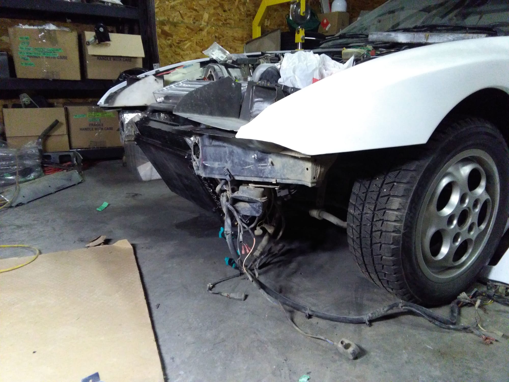
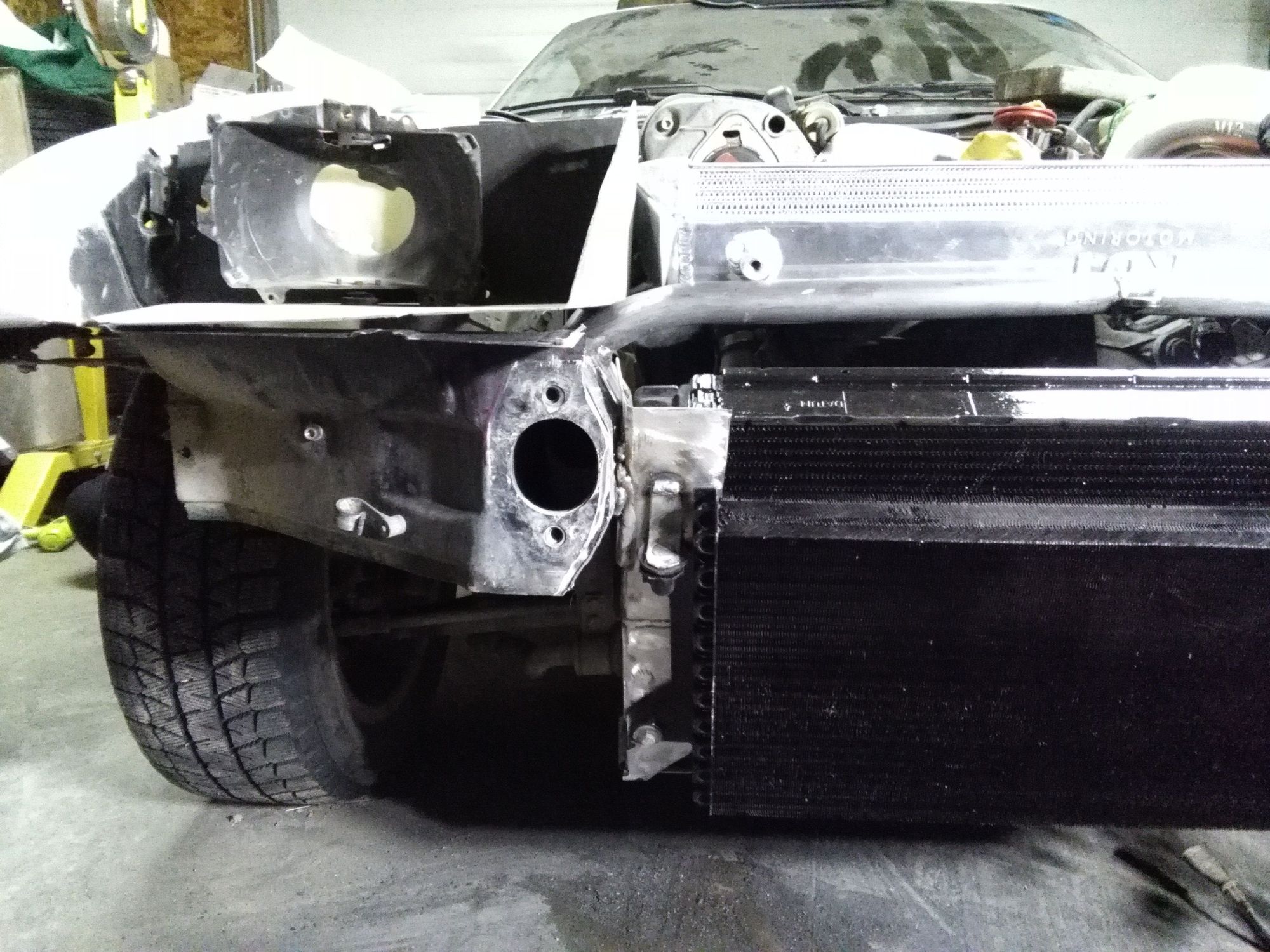
At long last I now have the rad & a/c condenser tacked onto the frame rails. This and air flow will determine the third tubular crossmember position.
The new intercooler position will require a turbo position change.
 |
|
| Back to top |
|
 |
morghen

Joined: 21 Jan 2005
Posts: 8879
Location: Romania
|
| Posted: Sat Mar 04, 2017 7:10 pm Post subject: |
|
|
Thats kind of low for a radiator to hang around isnt it?
Your intercooler position is half in a positive pressure zone half in a slightly negative zone, what is the direction you want to air to flow trough it?
_________________
https://www.the924.com |
|
| Back to top |
|
|
Noahs944
Joined: 08 Dec 2015
Posts: 782
Location: Calgary, Alberta, Canada
|
| Posted: Sun Mar 05, 2017 2:03 am Post subject: |
|
|
Morghen,
Must be an optical illusion. Yes I mounted the rad as low as possible (for centre of gravity) but it's no lower than the swaybars.
Had a really good chat with Mike Lindsey about front mounted intercoolers and a/c. He once had a customer pay LR to install a front mounted IC that didn't fit well at all. Mounted in front of condenser. Hot hot summer weather. POP! compressor line blows.
What happened was the high pressure side got so hot that the a/c compressor locked up. |
|
| Back to top |
|
|
Noahs944
Joined: 08 Dec 2015
Posts: 782
Location: Calgary, Alberta, Canada
|
| Posted: Sun Mar 05, 2017 2:38 am Post subject: |
|
|
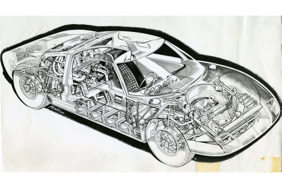
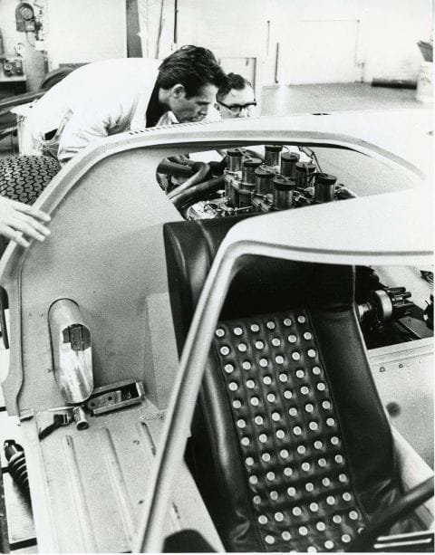
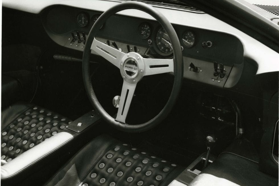
This diagram shows airflow in and out of the GT40. Note the vented seats that exhaust through the roof ports. The large door duct is an interesting detail. Also note the brake cooling inlets near the front radiator and aft of the door opening.
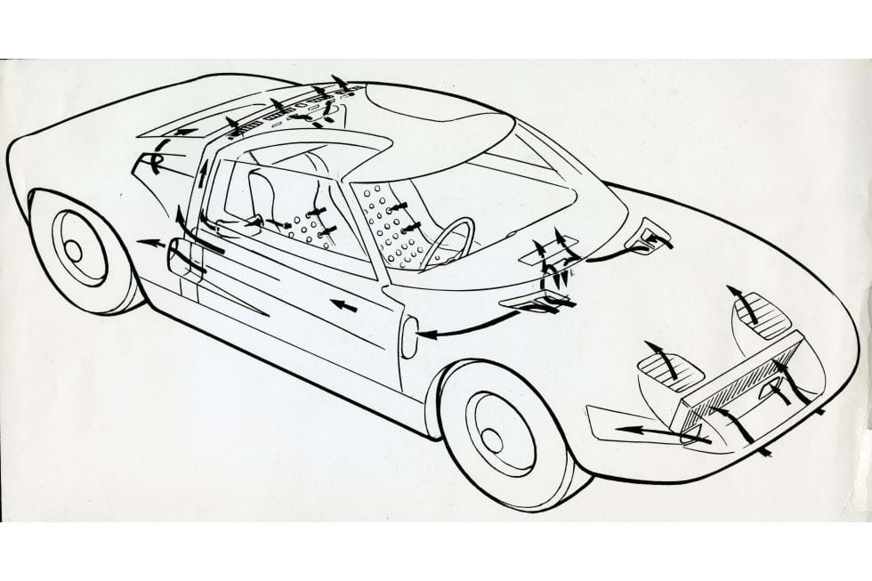
Ford of Britain captioned this photo: "The driver's seat in the new Ford GT is air conditioned. Air which is drawn in at the front of the car circulates throughout the whole of the seat to ensure that any perspiration which is generated by the driver during the race is quickly evaporated."
 |
|
| Back to top |
|
|
Noahs944
Joined: 08 Dec 2015
Posts: 782
Location: Calgary, Alberta, Canada
|
| Posted: Sun Mar 05, 2017 3:06 am Post subject: |
|
|
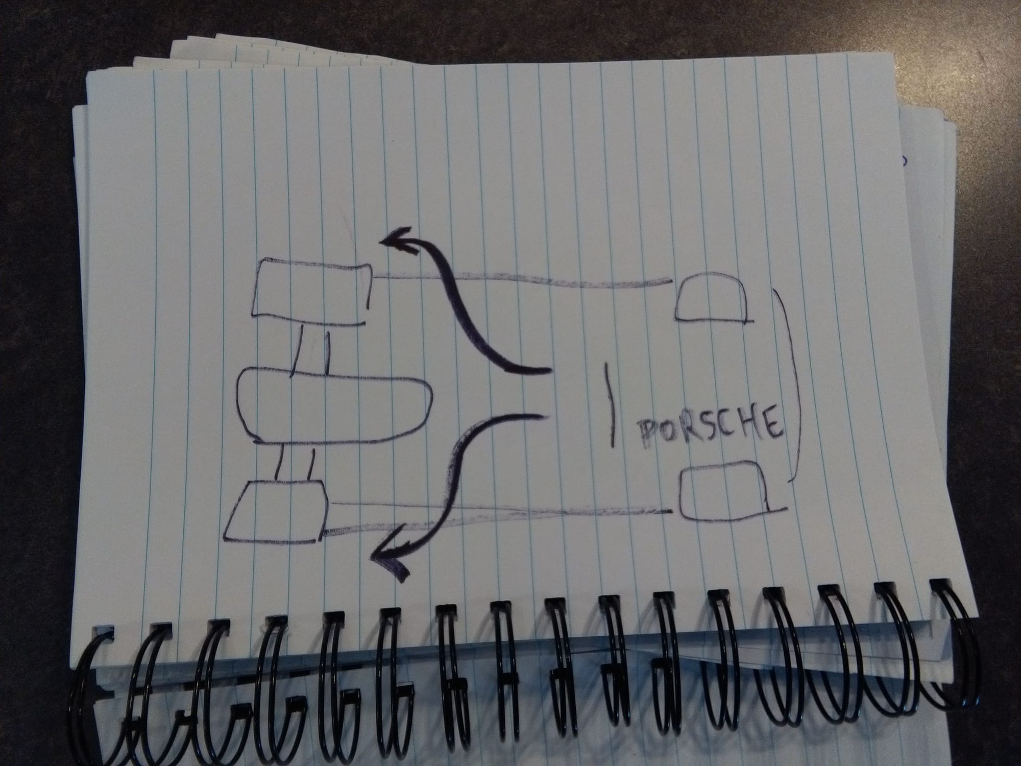
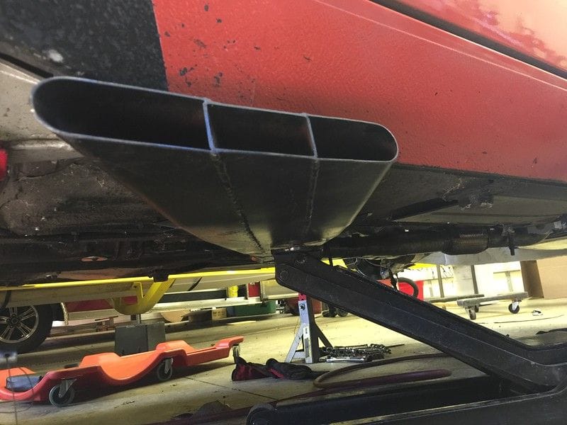
Been thinkin' lately on the under belly.
Startin' to think that creating an arrowhead shape to guide the undertray air out of the car before the transaxle might be a good idea. If the exhaust split into 2 side pipes, that might just do it. Thoughts?
 |
|
| Back to top |
|
|
Noahs944
Joined: 08 Dec 2015
Posts: 782
Location: Calgary, Alberta, Canada
|
| Posted: Sun Mar 05, 2017 8:22 am Post subject: |
|
|
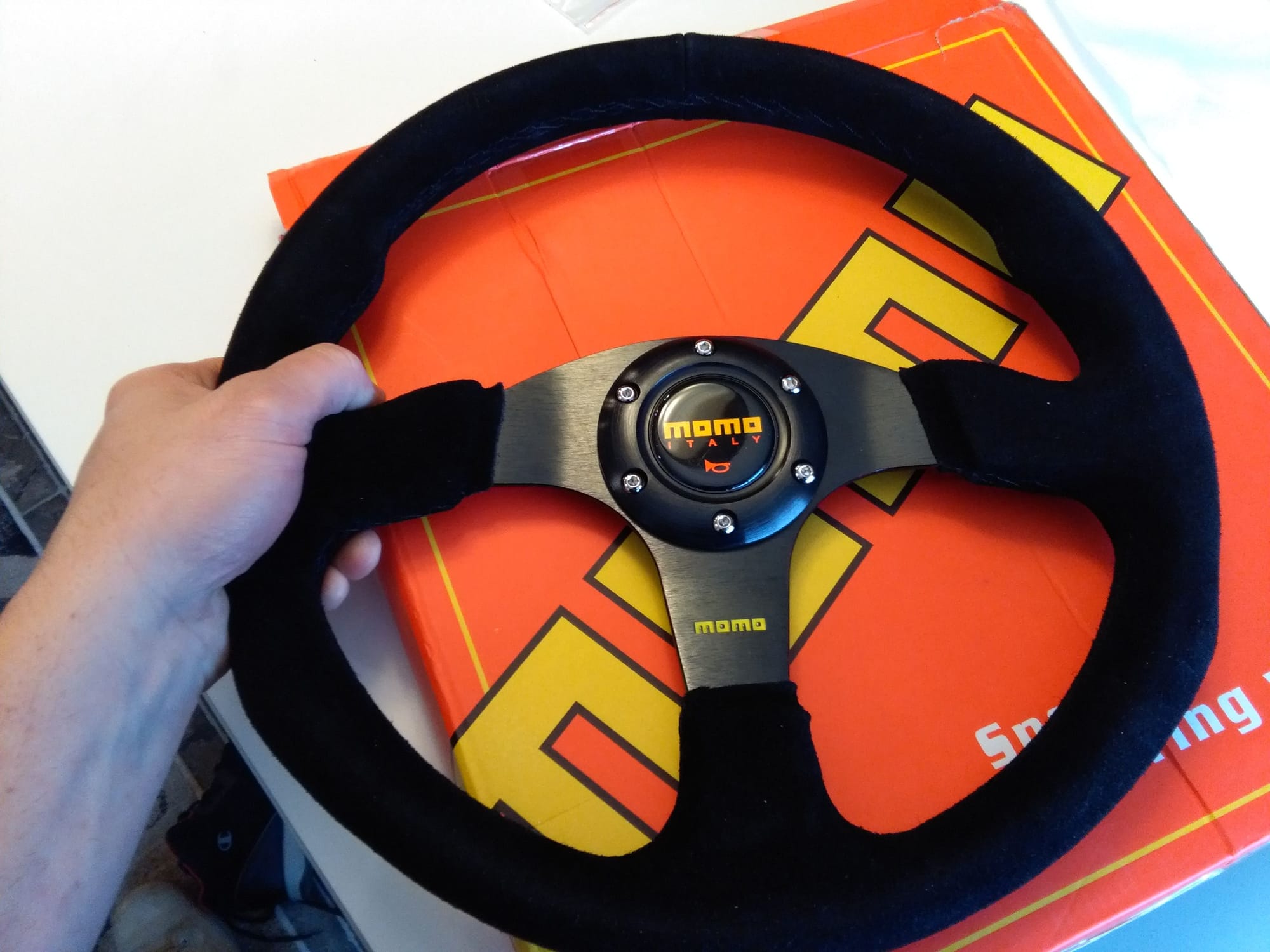
Planning on making a steering wheel adapter using an old beat up 4 spoke 944 Porsche steering wheel.
Probably using this flat Suede covered wheel..... mmmmm, so nice!
 |
|
| Back to top |
|
|
Fasteddie313

Joined: 29 Sep 2013
Posts: 2596
Location: MI
|
| Posted: Sun Mar 05, 2017 10:20 am Post subject: |
|
|
| Noahs944 wrote: | Been thinkin' lately on the under belly.
Startin' to think that creating an arrowhead shape to guide the undertray air out of the car before the transaxle might be a good idea. If the exhaust split into 2 side pipes, that might just do it. Thoughts?
|
I think the point of ground effect, like that lotus video I showed you, is to have a low front to push the air away from under the car, and low side skirts to minimise te amount of air that can come in from the sides, and then a large opening in the rear where their is a vacuum behind the car..
So therefore it creates a vacuum under the car and sucks it down to the road..
That steering wheel is beautiful..
_________________
80 Turbo - Slightly Modified |
|
| Back to top |
|
|
Noahs944
Joined: 08 Dec 2015
Posts: 782
Location: Calgary, Alberta, Canada
|
| Posted: Mon Mar 06, 2017 11:30 am Post subject: |
|
|
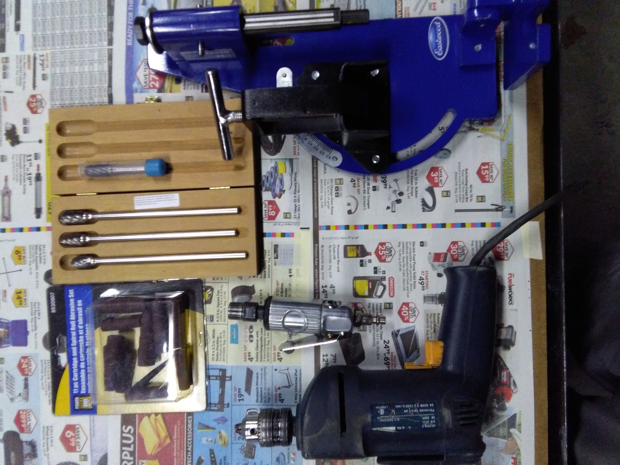
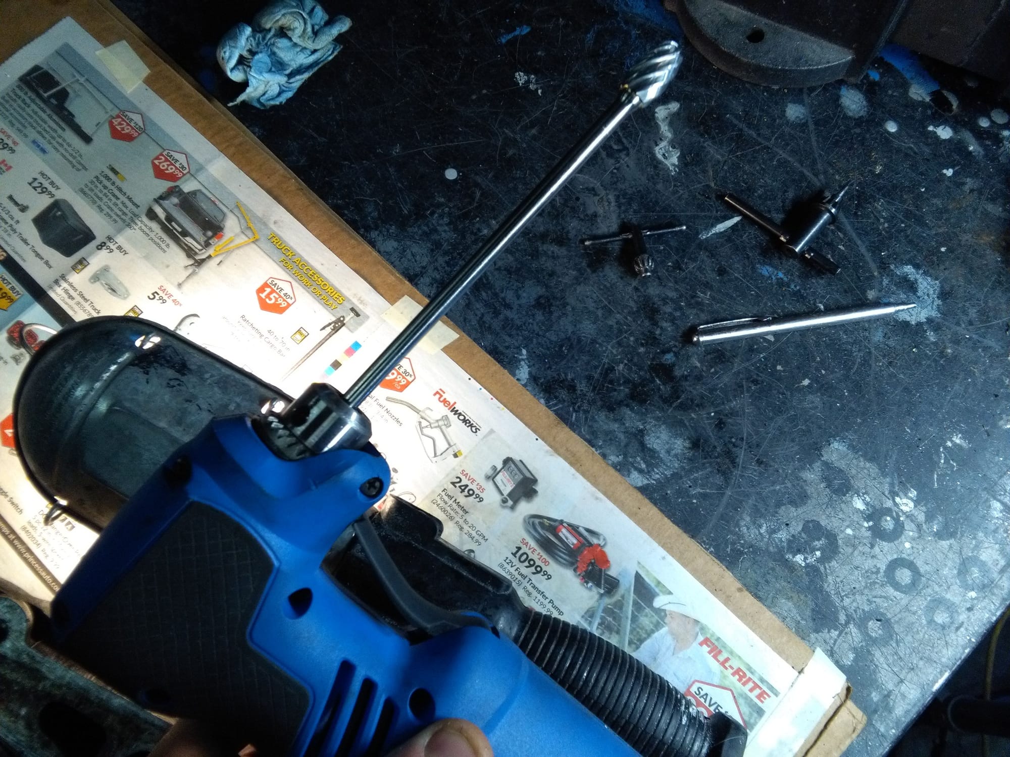
I'm going to attempt my own mild head work on one of these spare heads. The pipe notcher is hopefully going to allow me to undercut the valves.
http://www.hotrod.com/articles/valve-angle/
My plan for the head is simple. Stock compression 8:1 head, stock n/a head with mild porting and also 30 degree undercutting of the intake valves. Besides that, just a simple re-lapping of the valves & replace the valve guide seals. Also gasket-match the intake & exhaust ports. Lastly, i will install new turbo grade valve springs. And just give the head an inspection for warpage and thread damage.
Not sure if undercutting the exhaust valves is recommended. Considered bumping compression to 8.5:1, but that means two trips to the city... though I think it would make for a faster car at autocross & around town.
I haven't done this type of work before.
 |
|
| Back to top |
|
|
Noahs944
Joined: 08 Dec 2015
Posts: 782
Location: Calgary, Alberta, Canada
|
| Posted: Wed Mar 08, 2017 1:27 pm Post subject: |
|
|
So pumped!! Now all I have to do is figure out how to mount this!

 |
|
| Back to top |
|
|
Noahs944
Joined: 08 Dec 2015
Posts: 782
Location: Calgary, Alberta, Canada
|
| Posted: Mon Mar 13, 2017 5:49 am Post subject: |
|
|
Because of the v-mount rad and with respect to reducing air flow obstacles I will try to alter the water neck angle to the upper radiator.
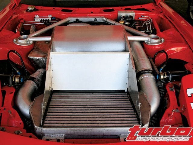
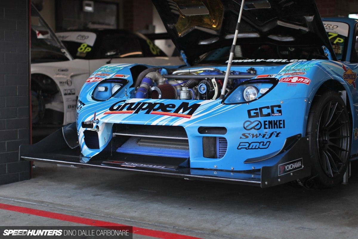
By the way, there are different takes/methods to "v mount" here are 2 types:
Notice the "dam" on the sides to prevent the air going the path of least resistance.
Notice the smooth ramp the builder created to guide the air in. Beautiful car!!
 |
|
| Back to top |
|
|
Noahs944
Joined: 08 Dec 2015
Posts: 782
Location: Calgary, Alberta, Canada
|
| Posted: Mon Mar 13, 2017 6:14 am Post subject: |
|
|
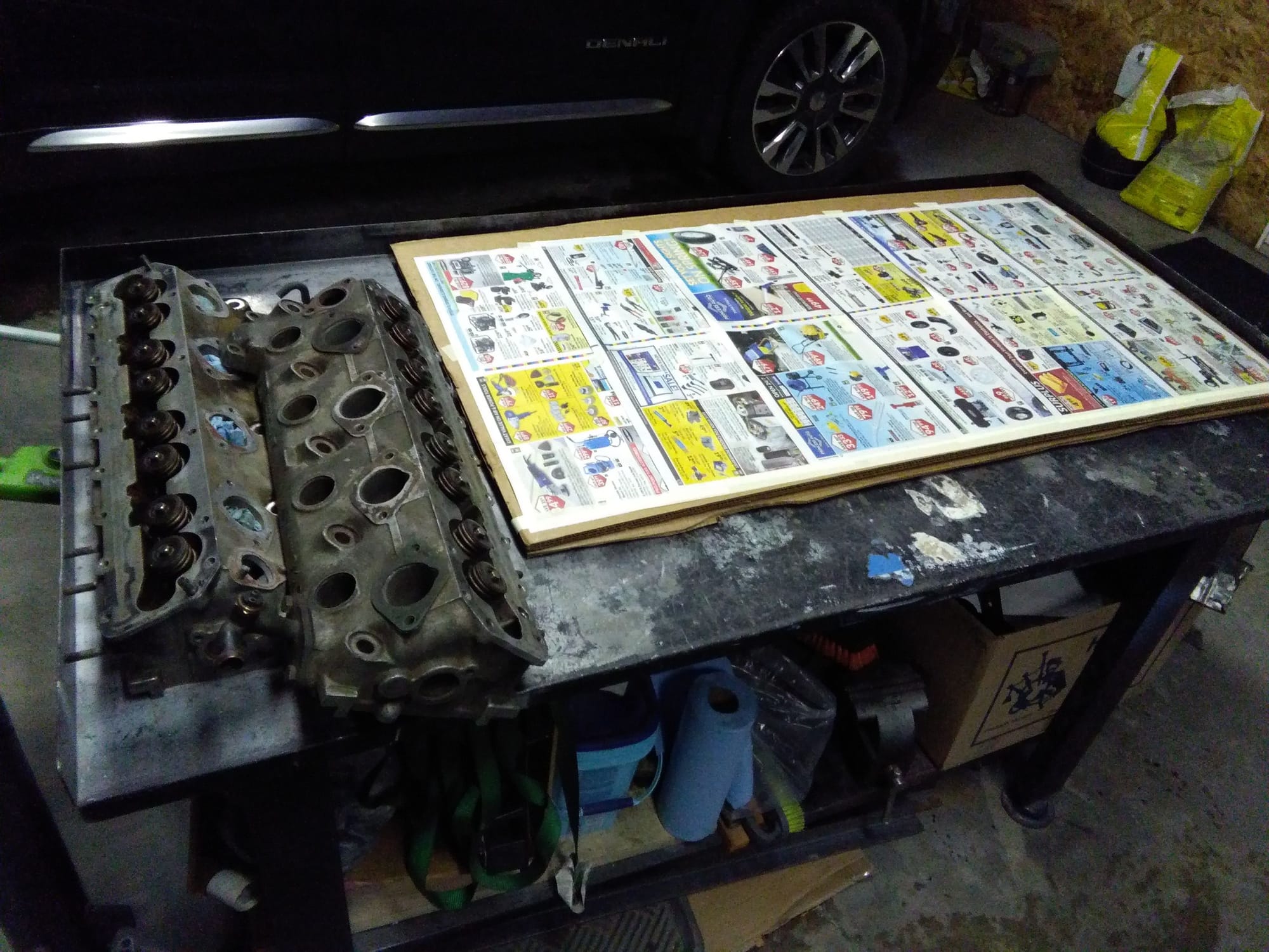
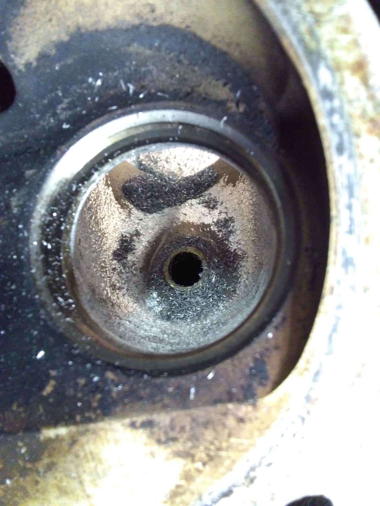
[LEFT]Okay, before I can trust this head I need to assess the condition. Disassemble using magnet to acquire the valve retainer keepers.

I am hoping to do all of the head repairs & mods by myself. This head looks rough in a couple of areas, for instance the 2 broken studs for the water neck were severed when I got it. After attempts to weld nuts and wrench them out were unsuccessful, then I tried drilling & using easy-out removal tools (which of course did not work). Then I tried drilling through and tapping. I managed to drill an tap the bottom bolt but my drill bit broke in the upper bolt. That doesn't really matter though because I don't plan on using the top bolt hole.
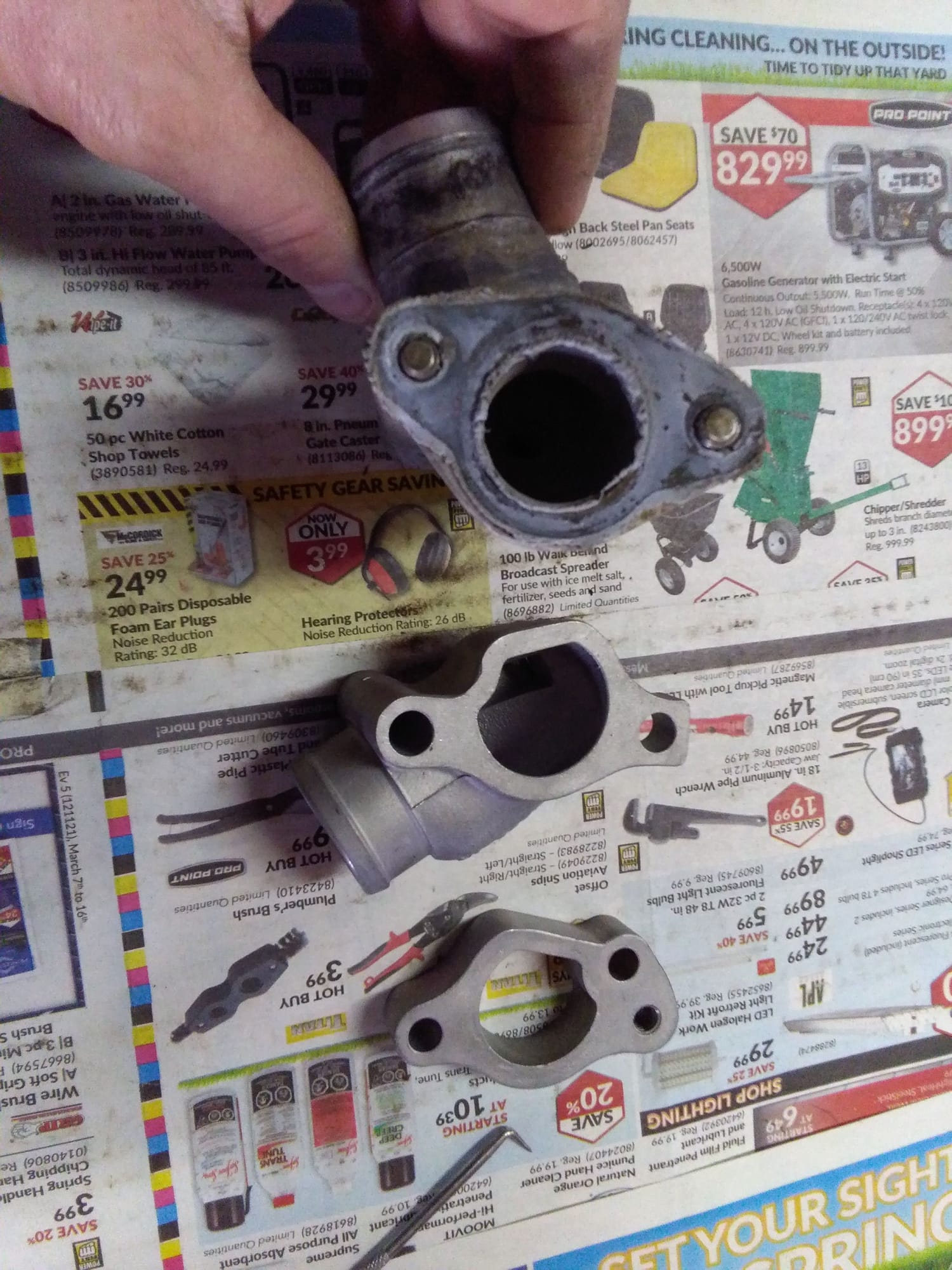
Top: 8 valve neck, bottom 16 v which points to the driver's fender versus the rad.
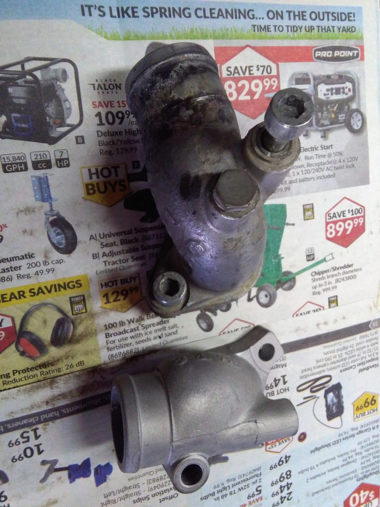
The 16v neck isn't shaped the same where it'll meet the head unfortunately, but maybe it can be modded. Notice the spacer.
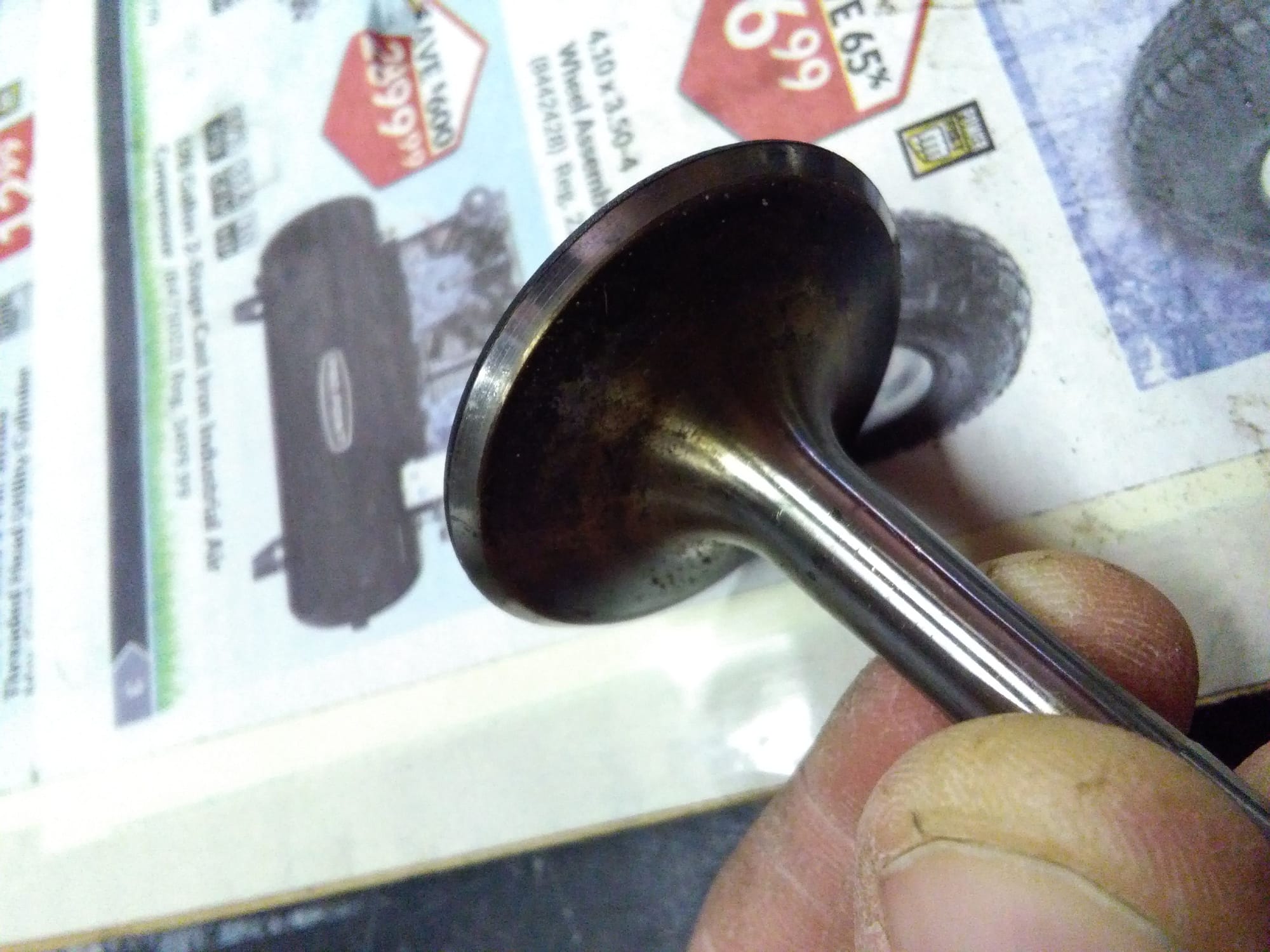
Assessing the condition. Valve surfaces shouldn't be "cupped" or worn, where the valve head seats. They should appear flat on the machined bevel. This looks like it could use a quick hand powered "valve lap" and be good to go! As each valve and spring and spacer & retainer is removed from the head, it is placed in a particular order on the bench (i.e. cyl #1 intake).
 [/LEFT] [/LEFT] |
|
| Back to top |
|
|
Noahs944
Joined: 08 Dec 2015
Posts: 782
Location: Calgary, Alberta, Canada
|
| Posted: Mon Mar 13, 2017 6:15 am Post subject: |
|
|
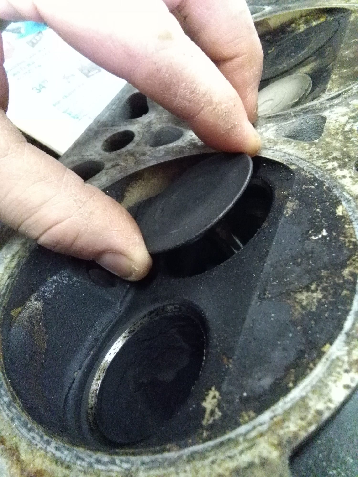
YES!! Woohoo! These intake ports have a 5 angle grind already!!:rockon: This is something I wanted but was going to forgo because not in the budget. Awesome:thumbsup:
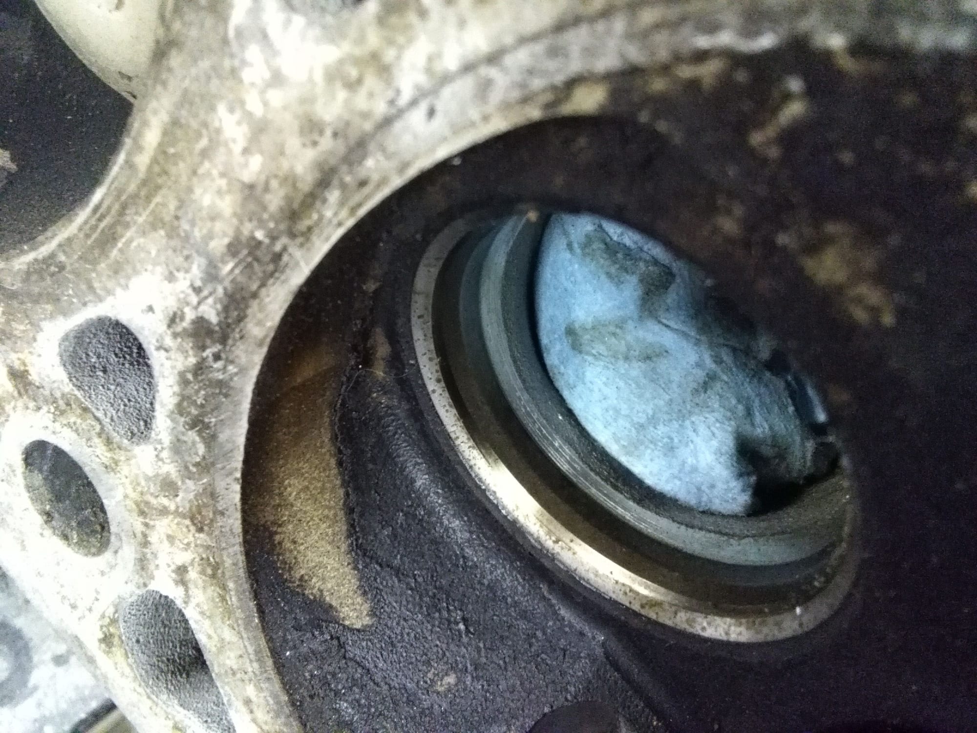
I check the valve guide wear with the springs removed and at 10mm "lift" in the direction of wear a little play is okay. These guides are not worn out so I will reuse. The last head I had apart had twice this radial movement and the valve seat were cupped... I think worn guides wear out seats.
 |
|
| Back to top |
|
|
Noahs944
Joined: 08 Dec 2015
Posts: 782
Location: Calgary, Alberta, Canada
|
| Posted: Mon Mar 13, 2017 7:17 am Post subject: |
|
|
Some respected builder Chris White taken out from several of his responses on a thread regarding turbo head modifying.
"If you must port and polish then polish the outside of the head and buy a nice port wine and drink it.
The good old days of porting and polishing died a while ago. The bigger hole more air more power theory does not apply. The interactions of the shape/texture/design of the intake ports and the production of power is seriously complex and, as any decent head man will tell you, not scientifically well defined.
The most important product of modern cylinder head design is the turbulence created in the combustion chamber a pretty tough thing to measure. The propagation of the frame front can be greatly effected by the turbulence, by as much as a factor of two. The speed of propagation has every thing to do with controlling detonation and achieving favorable conditions for additional ignition timing. So if anybody thinks they can grab a die grinder and alter their ports to add turbulence to the combustion chamber good luck.
Back in the days when I helped out on the Trans Am circuit I got to see the real high dollar heads and you would swear that they wouldnt work well. They were the result of a little science and a lot of trail and error. If you have 30 or 40 heads to experiment on (the results can only be shown on the dyno so you will need to assemble and test each engine) then you might be able to show some real improvement.
That being said it doesnt hurt to clean up any casting abnormalities and maybe clean up the valve guide casting area. A good valve job will get good results.
PS - the turbo may create some turbulence at the compressor but after it has traveled through the intercooler and quite a bit of piping and the throttle body the turbulence is pretty much "straightened out."
Oh yeah one other issue on head texture remember that at any kind of real load the fuel injector will be squirting fuel at a closed valve. 80% duty cycle refers to the injector firing for 80% of the complete 4 cycle. Batch fired systems fire twice per each 4 cycle (720 degree) occurrence. One shot will be during the intake cycle but the other one will be 180 degrees out. The texture of the walls can effect the wetting factor. Very smooth surfaces tend to increase the amount of fuel that will come out of suspension.
Just as a point of interest the Tec3 system even has an adjustment factor for the amount of intake port wetting. If you have a set up that really encourages intake wetting then you will see an initial lean out when opening the throttle. This is because the fuel is sucked of the walls during a closed throttle decelerating condition and when you first crack the throttle a certain amount of fuel will drop out of suspension to rewet the walls.
Polish the outside
.
Think systems approach.
If you bolt that head on an other wise completely dead stock engine then it will not do anything special and quite possibly drop off your low to mid range torque just a tad.
If you really want modifications, especially those directly effecting the air flow, to work you need to make sure that the system is modified or adjusted to accommodate the mod. So if you are bolting that head on an engine that has a larger turbo, different wastegate set to a higher boost level, modified engine management then it may well make more HP.
Another thing to keep in mind when I use the catch word system you need to define what you want to accomplish (and more performance is not an acceptable answer!)
Defining what you want to accomplish is a very important step in modifying and dont take it too lightly as there are consequences for every action.
Do you want more max HP? Then you will give up low to midrange torque.
Do you want to support more boost? Then you will not have as good spool up or off boost response.
To a certain extent its all give and take, so defining your goal and understanding the implications is pretty important."
Chris White |
|
| Back to top |
|
|
Noahs944
Joined: 08 Dec 2015
Posts: 782
Location: Calgary, Alberta, Canada
|
| Posted: Mon Mar 13, 2017 8:13 am Post subject: |
|
|
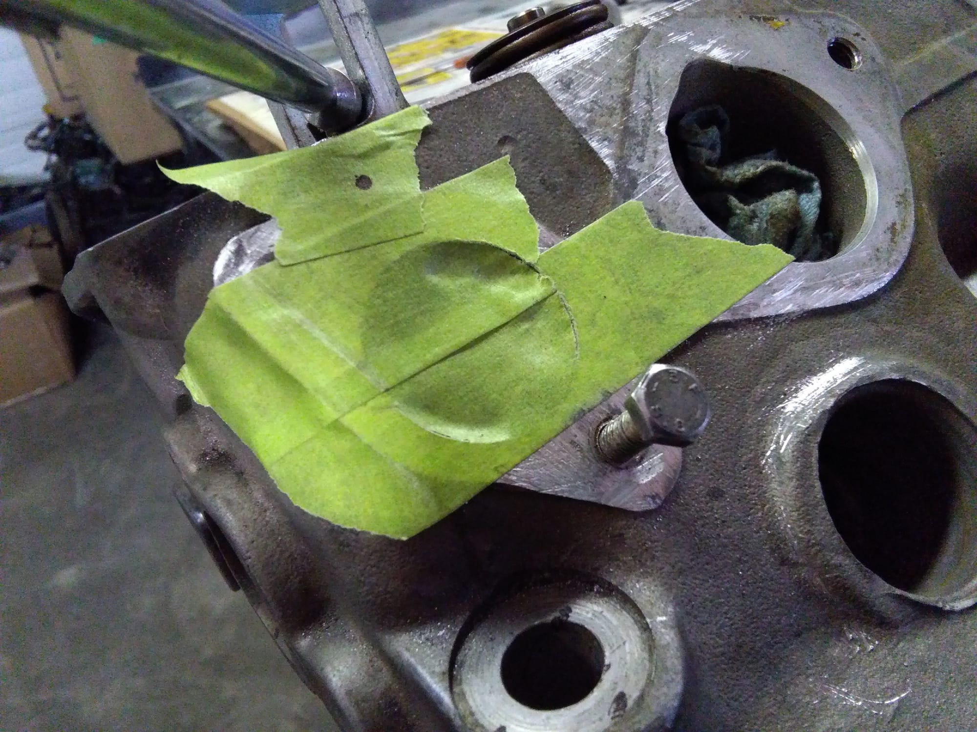
WOOHOO! My first time doing a porting job.
That is just 20 minutes (aluminum head & new $$$ grinding bit) from Snapon.
 |
|
| Back to top |
|
|
Noahs944
Joined: 08 Dec 2015
Posts: 782
Location: Calgary, Alberta, Canada
|
|
| Back to top |
|
|
|

