| View previous topic :: View next topic |
| Author |
Message |
Matilda
Joined: 17 Apr 2012
Posts: 30
Location: London, Ontario, CA
|
 Posted: Thu Apr 19, 2012 11:08 am Post subject: 931.606.021.00 Pulse sender, flywheel sensor? 1981 924 Turbo Posted: Thu Apr 19, 2012 11:08 am Post subject: 931.606.021.00 Pulse sender, flywheel sensor? 1981 924 Turbo |
 |
|
All,
I've got this 1981 924 Turbo. No start, no spark.
I'm starting with this "pulse sender"... or crank sender... flywheel sensor...((I'm finding many names for this))
Porsche has the part number: 931.606.021.00
I can see a part number on it: 5WK1517. Although... Other websites say "5WK7517". The "4th" segment looks like a "1" to me 
I'm trying to figure out if this part has failed. Does anyone know how to test it? Does anyone have a working unit they can take measurements from?
On my unit, I'm measuring the following:
pins 13 to 15 0.46 ohms.
pins 13 to 14 8.47 ohms.
pins 14 to 15 8.68 ohms.
I had a look inside the DITC unit right where this pulse sender plugs in. Pins 13 & 14, both start off by going through a set of box capacitors. This tells me the sensor is probably a VR sensor (Variable reluctance). Not a Hall Effect.
So, with sensor installed at the flywall, and with engine cranking, I looked for an AC voltage across pins. 13/14, 14/15 and 13/15... nothing.
Any info would be great!
It would be great to know if the sensor is Hall Effect... or VR.
I also put the car back together, and scoped pins 13,14 & 15 (wrt ground) of this sensor, inside the DITC, while cranking the engine. Nothing
Help?  |
|
| Back to top |
|
 |
Matilda
Joined: 17 Apr 2012
Posts: 30
Location: London, Ontario, CA
|
| Posted: Thu Apr 19, 2012 11:52 am Post subject: |
|
|
I'm looking through other threads, and I see this picture....
Who has this book?
I can see my pulse sender (3 pin) at the top.... does it say anything for me 
 |
|
| Back to top |
|
|
Rasta Monsta

Joined: 12 Jul 2006
Posts: 11724
Location: PacNW
|
| Posted: Thu Apr 19, 2012 2:27 pm Post subject: |
|
|
Here is the FSM page:
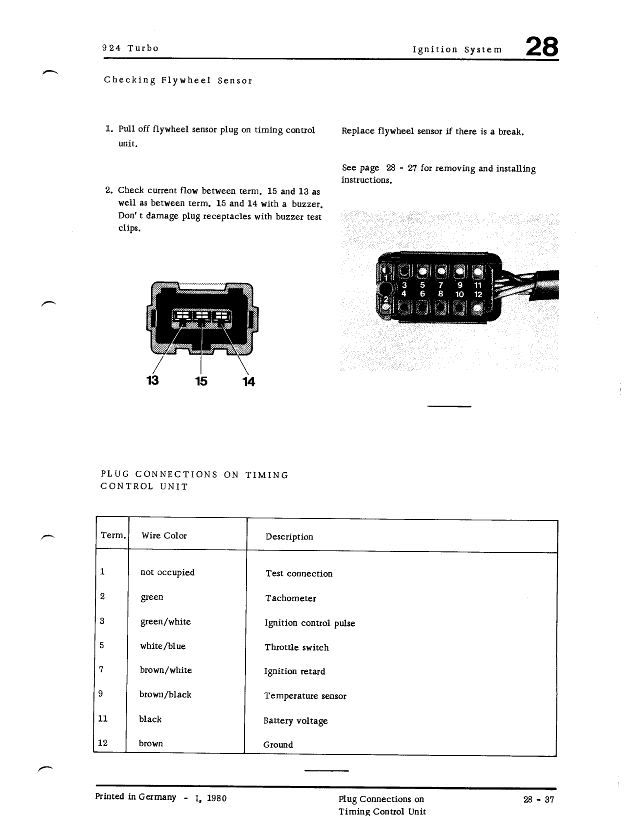
Looks like it is calling for continuity testing between 15/13 and 15/14. Based on your results above, seems like the sensor is bad.
I seem to recall someone saying the same part is used as a TDC sensor for dealer diagnostic equipment on 944, 928, and 911 3.2 (part 911 606 108 00, also NLA).
_________________
Toofah King Bad
- WeiBe (1987 924S 2.5t) - 931 S3
|
|
| Back to top |
|
|
Matilda
Joined: 17 Apr 2012
Posts: 30
Location: London, Ontario, CA
|
| Posted: Thu Apr 19, 2012 9:50 pm Post subject: |
|
|
Super Thanks Rasta,
Is there any further info in the FSM about this buzzer? (Its setup) The test info is a little vague. I'm wondering if there is a special test jig porsche Techs use?
I'm a little confused....
Is there a little buzzer that goes off when the car cranks?
Or do you power a buzzer in series with the sensor? If this sensor is working.... I don't want to blow it.
My next plan is to either feed an AC voltage (say 2V p-p) from a function generator into the DITC, and crank the engine. I want to see if I get spark.
Or, what would be nice is know what the signal looks like at the ignition module, from the DITC. (Pin #6, Ignition control pulse). And then provide that signal from a function generator. |
|
| Back to top |
|
|
ideola

Joined: 01 Oct 2004
Posts: 15548
Location: Spring Lake MI
|
| Posted: Thu Apr 19, 2012 9:55 pm Post subject: |
|
|
The diagnostic sensor on the 944 is NOT the same as this one.
All you're looking for is continuity between the pins as described. Any decent multi-meter should have a continuity tester with a built-in buzzer. So you put the + lead on 13 and the - lead on 15, with the mm set to continuity, it should buzz. If it doesn't there's your problem. Repeat for 14-15.
_________________
erstwhile owner of just about every 924 variant ever made |
|
| Back to top |
|
|
Matilda
Joined: 17 Apr 2012
Posts: 30
Location: London, Ontario, CA
|
| Posted: Thu Apr 19, 2012 11:06 pm Post subject: |
|
|
| ideola wrote: | | All you're looking for is continuity between the pins as described. Any decent multi-meter should have a continuity tester with a built-in buzzer. So you put the + lead on 13 and the - lead on 15, with the mm set to continuity, it should buzz. If it doesn't there's your problem. Repeat for 14-15. |
Yes, I have an excellent meter. I have Fluke meters and scopes on hand.
First, when measuring in ohms, there is no polarity with meter leads.
According to fluke, continuity between two points is anything less than 24Ω
I have just checked both my meters using a 22Ω and 27Ω resistors.
In my test, I was measuring 8.67Ω. So yes, if I used the continuity test the meter would Buzz.
I need to do some more digging.
I don't think a buzzer test is right.... unless what they means is, if one does get a buzz (Continuity), then the sensor is pooched.
From my experience with VR (Variable reluctance) sensors, the resistance can range from 150Ω to 340Ω.
I know it would be some work, but if someone could take some resistance measurements of a working sensor... that would be great
 [/img] [/img] |
|
| Back to top |
|
|
ideola
Joined: 01 Oct 2004
Posts: 15548
Location: Spring Lake MI
|
| Posted: Fri Apr 20, 2012 12:17 am Post subject: |
|
|
On my two spares:
Spare 1: 13-15 => continuity; resistance = 00.7
Spare 1: 14-15 => continuity; resistance = 08.9
Spare 2: 13-15 => continuity; resistance = 00.7
Spare 2: 14-15 => continuity; resistance = 08.9
_________________
erstwhile owner of just about every 924 variant ever made |
|
| Back to top |
|
|
Matilda
Joined: 17 Apr 2012
Posts: 30
Location: London, Ontario, CA
|
| Posted: Fri Apr 20, 2012 12:34 am Post subject: |
|
|
Hmmmm..... that is interesting. Thats what I got.
I guess whats bugging me is.... 8Ω seems so low.
And these are good crank sensors?? Or unknowns? |
|
| Back to top |
|
|
ideola
Joined: 01 Oct 2004
Posts: 15548
Location: Spring Lake MI
|
| Posted: Fri Apr 20, 2012 1:11 am Post subject: |
|
|
| Matilda wrote: | Hmmmm..... that is interesting. Thats what I got.
I guess whats bugging me is.... 8Ω seems so low.
And these are good crank sensors?? Or unknowns? |
Removed from running cars that were wrecked.
_________________
erstwhile owner of just about every 924 variant ever made |
|
| Back to top |
|
|
Matilda
Joined: 17 Apr 2012
Posts: 30
Location: London, Ontario, CA
|
| Posted: Fri Apr 20, 2012 1:33 am Post subject: |
|
|
Knowing that you've got the same resistances as me, I'm going to take another look at the output of the sensor. The photo below shows how to read a VR sensor.... again, I'm assuming thats what this is.
The only difference is, I didn't add a resistor. Like the one shown. 2.7KΩ.
I guess it's need to complete the circuit. I'l then place my meter across the resistor on AC.
I don't think I'll see anything different. As I scope all 3 lines from this sensor inside the DITC while cranking the engine. Key On.
 |
|
| Back to top |
|
|
Matilda
Joined: 17 Apr 2012
Posts: 30
Location: London, Ontario, CA
|
| Posted: Fri Apr 20, 2012 5:41 am Post subject: |
|
|
| ideola wrote: | | Removed from running cars that were wrecked. |
Questions...
Would you be willing to sell?
Or,
Willing to test my DITC and cable in a running car?
Bob |
|
| Back to top |
|
|
ideola
Joined: 01 Oct 2004
Posts: 15548
Location: Spring Lake MI
|
| Posted: Fri Apr 20, 2012 6:29 am Post subject: |
|
|
| Matilda wrote: | Questions...
Would you be willing to sell? |
Gaaaahhh. Urrrrrrgggh. I don't think so...I have 3 cars that rely on DITC, and I'm nervous as hell about not having backups for all of them.
| Matilda wrote: | Or,
Willing to test my DITC and cable in a running car? |
There's a slightly better chance I might be willing to do this, but man is it a royal PITA dealing with that thing on an in situ motor!
I went out and tested the sensor on my 81, and it gives EXACTLY the same readings as the two spares I have on the shelf, so if your sensor is reading just like mine, it doesn't seem like that's the culprit.
I have several spare DITC boxes lying around...what I want to do is compare them to your photos. Let's do that before I commit one way or the other on the crank sensor.
So as I'm understanding it, you are absolutely 100% certain you are not getting spark signal to the coil itself???
_________________
erstwhile owner of just about every 924 variant ever made |
|
| Back to top |
|
|
Matilda
Joined: 17 Apr 2012
Posts: 30
Location: London, Ontario, CA
|
| Posted: Fri Apr 20, 2012 7:09 am Post subject: |
|
|
| ideola wrote: |
So as I'm understanding it, you are absolutely 100% certain you are not getting spark signal to the coil itself??? |
Ummmm... not myself. But the mechanic who has the car says Yes.
We have also tried a new Ignition module.
Power and grounds look good. Battery has great connections.
I measured Ground and 12V at the DITC.
I should also add, when I'm cranking the engine, the tach needle doesn't move. I've read that it should? (At least flutter around?)
I'm going back to the car tomorrow. I'll hook my scope up to the pin #1 of the ignition module (Same connection as pin #1 of coil) and confirm there is no signal. |
|
| Back to top |
|
|
ideola
Joined: 01 Oct 2004
Posts: 15548
Location: Spring Lake MI
|
| Posted: Fri Apr 20, 2012 7:10 am Post subject: |
|
|
Yeah, the tach needle should bounce (but not wildly flop) while cranking...
_________________
erstwhile owner of just about every 924 variant ever made |
|
| Back to top |
|
|
924RACR

Joined: 29 Jul 2001
Posts: 8817
Location: Royal Oak, MI, USA
|
| Posted: Fri Apr 20, 2012 9:42 pm Post subject: |
|
|
Heh heh... just realized you're over in London. Figured you'd show up here eventually; I got an inquiry on another board from another shop than the one that's been working on your car, asking about the sensor... 
Too bad my car's not together at the moment, or we could consider using it as a test.
Don't forget that the rest of the wiring can very easily be suspect...
_________________
Vaughan Scott
Webmeister
'79 924 #77 SCCA H Prod racecar
'82 931 Plat. Silver
#25 Hidari Firefly P2 sports prototype |
|
| Back to top |
|
|
|

