| View previous topic :: View next topic |
| Author |
Message |
Fasteddie313

Joined: 29 Sep 2013
Posts: 2596
Location: MI
|
 Posted: Thu Jun 11, 2015 1:05 pm Post subject: Help with compressor maps? Posted: Thu Jun 11, 2015 1:05 pm Post subject: Help with compressor maps? |
 |
|
Could someone that's a wiz at compressor maps throw these in paint and plot a well intercooled 931 engine @ 1bar - 1.5bar on this here map and post it back up?
these k27 cold sides can be easily had very cheap, is it any good for our engines?
This is a 930 3LDZ..

How about this one? Its the 951 k26/8..

S1 931

_________________
80 Turbo - Slightly Modified |
|
| Back to top |
|
 |
morghen

Joined: 21 Jan 2005
Posts: 8884
Location: Romania
|
| Posted: Thu Jun 11, 2015 3:44 pm Post subject: |
|
|
You can use the cold side and the compressor wheel off a K27 on a K26.
I did that a few years ago and the result is pretty fast. But i didnt use the 911 compressor and wheel. That one has a too large inducer and you will get a quite laggy feel. Instead i used an earth mover K27 with a smaller inducer than the 911 but still 15% larger than the K27.
The problem with the old k26 isnt really flow, but efficiency. It will heat up the charge at higher flows and pressures. The K27 will keep cooler for more flow.
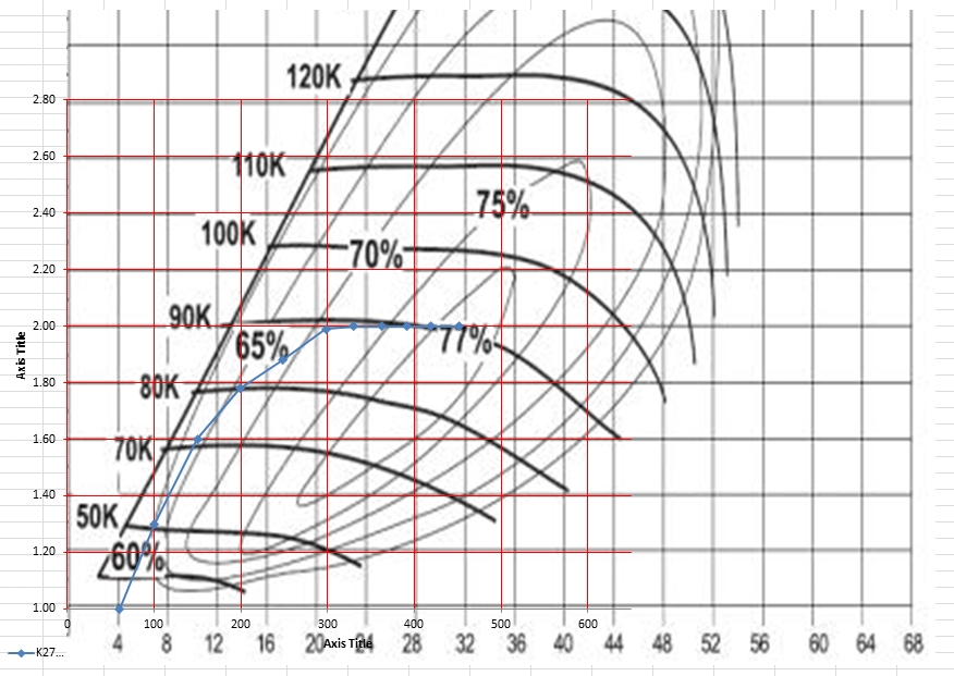
My estimations, observations and calculations lead to the following plot.
By 2000RPM it is already into the 60% efficiency isle which is not bad at all.
By 3000RPM its already passed into 65% isle
Before 4000RPM it goes into 70% isle and from there on to 6000-6500RPM the compressor gets more and more efficient.
The feel is that the car starts to pull as the normal 931 does until 3000RPM but after that it pulls harder and harder until you have to change gear and then until you run out of gears 
Here you go:
_________________
https://www.the924.com |
|
| Back to top |
|
|
Fasteddie313
Joined: 29 Sep 2013
Posts: 2596
Location: MI
|
| Posted: Thu Jun 11, 2015 4:48 pm Post subject: |
|
|
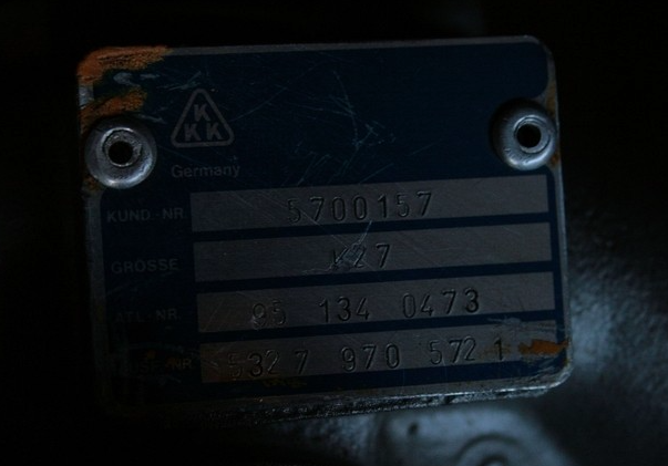
I would love the turbo numbers off the blue tag of that k27 you're using, and that that map is for correct?
_________________
80 Turbo - Slightly Modified |
|
| Back to top |
|
|
Cedric

Joined: 27 Aug 2004
Posts: 2614
Location: Sweden
|
| Posted: Thu Jun 11, 2015 5:01 pm Post subject: |
|
|
Dont forget the pressure before the compressor, you would probably reach 2.2 pr in the map at 1 bar of boost.
_________________
1980 924 Turbo
www.instagram.com/garagecedric/ |
|
| Back to top |
|
|
morghen
Joined: 21 Jan 2005
Posts: 8884
Location: Romania
|
| Posted: Thu Jun 11, 2015 6:12 pm Post subject: |
|
|
Good point about the pressure before the compressor. But one can take the sea level value as the safe point as for a street car one has to worry about overboosting.
This is what i'm using:
_________________
https://www.the924.com |
|
| Back to top |
|
|
Cedric
Joined: 27 Aug 2004
Posts: 2614
Location: Sweden
|
| Posted: Thu Jun 11, 2015 8:48 pm Post subject: |
|
|
Altitude is one thing. But pressure drop over the air intake system and cis plate is significant.. Look at the 924 map posted above,will give some hints.
Also don't forget that you downspeed the turbine withe larger diameter k27. Which will move both efficiency and swallowing capacity at your running points. How efficiency changes is hard to say without a turbine map.
_________________
1980 924 Turbo
www.instagram.com/garagecedric/ |
|
| Back to top |
|
|
morghen
Joined: 21 Jan 2005
Posts: 8884
Location: Romania
|
| Posted: Thu Jun 11, 2015 9:33 pm Post subject: |
|
|
Well...so you mean the CIS plate, filter and tubes are acting as a restrictor.. I would not negate that, sure, but at what flow rate does the CIS start to be a real restricting factor?
Surely at lower flow rates its not creating any significant pressure drops. But at higher flow rates one would have to take into consideration such a thing.
As an example, to ideally flow 400BHP one would need a 2.5" diameter tube(taken from Corky's book).
The CIS plate flow area when lifted abot 30mm is larger than that.
Based on that thinking i ignored pre compressor pressure drop in my graph plot. Anyway, there are so many variables that its all an educated guess at best. Basically a bit of fun for a hungry brain and a bit of insurance that you're not doing it completely wrong.
In my case it works nicely, i had the impression that it is laggy, but its not...its just that the turbocharger has a larger inertia and needs more pedal from down low to get up to speed fast...otherwise it will pull itself up to speed later and it gets dramatic.
_________________
https://www.the924.com |
|
| Back to top |
|
|
Fasteddie313
Joined: 29 Sep 2013
Posts: 2596
Location: MI
|
| Posted: Fri Jun 12, 2015 1:44 am Post subject: |
|
|
5327-970-5721/5722 K27-3257MAA/13.21 Liebherr Earth mover...
Both have comp wheel 5327-123-2308 and comp housing 5327-101-5322, but that is the only 2 kkk's with that compressor so thats not going to be easy to find, prolly especially in USA where I've never heard of "Liebherr"...
Morghen if you ever need compressor side piston rings/piston/backplate etc this parts list may help.. http://www.turbomaster.info/despieces_3k/5327-988-5721.php
Can't find inducer/exducer specs for that wheel...
How did you manage to get a map for that?
Thats pretty cool if you're only running that turbo at 90k rpm like your plot says, it should last a long time that way..
_________________
80 Turbo - Slightly Modified |
|
| Back to top |
|
|
morghen
Joined: 21 Jan 2005
Posts: 8884
Location: Romania
|
| Posted: Fri Jun 12, 2015 4:27 am Post subject: |
|
|
Thanks for the link, i did alot of digging too.
I could not find info on the wheel either...but i'd like a billet one
Map is for the generic K27 compressor housing, the wheel and inducer/exducer details are a different thing.
I'm not saying you should get this compressor...it works nicely for me and it uses a smaller inducer wheel, that makes it spool up faster..but flow less.
But like i said in the previous posts, its no use to be able to efficiently flow much more with the turbo than the engine can. I'm happy with the choice i made, smaller inducer means less overall flow but quicker spool up.
I installed this hybrid turbo several years ago, i dont drive the car much...but when i do, i drive for long drives, thats 2-3k miles in a few days...or just 200-300mile one day trips...needless to say its still super clean, still boosts very hard, 1.1bar. I use relatively expensive and performant oil for these cars as well Motul 300V Competition oil...so that should extend the life of the turbo.
_________________
https://www.the924.com |
|
| Back to top |
|
|
ideola

Joined: 01 Oct 2004
Posts: 15548
Location: Spring Lake MI
|
| Posted: Fri Jun 12, 2015 4:29 am Post subject: |
|
|
The 3LDZ has crappy efficiency, like in the 60% range at best, not even worth considering. Much better and more plentiful options staying with the K26/7/8 family.
_________________
erstwhile owner of just about every 924 variant ever made |
|
| Back to top |
|
|
Fasteddie313
Joined: 29 Sep 2013
Posts: 2596
Location: MI
|
| Posted: Fri Jun 12, 2015 7:09 am Post subject: |
|
|
Could someone help me draw/plot a 931 engine, 7.5:1 comp, well intercooled, at 1bar - 1.5bar on the 951 k26/8 map and the 931 S1 2664 map (says Audi 5cyl but is the same compressor as 931 S1 2664)??
Like what morghen has on his k27 map..
_________________
80 Turbo - Slightly Modified |
|
| Back to top |
|
|
ideola
Joined: 01 Oct 2004
Posts: 15548
Location: Spring Lake MI
|
| Posted: Fri Jun 12, 2015 7:27 am Post subject: |
|
|
| Fasteddie313 wrote: | Could someone help me draw/plot a 931 engine, 7.5:1 comp, well intercooled, at 1bar - 1.5bar on the 951 k26/8 map and the 931 S1 2664 map (says Audi 5cyl but is the same compressor as 931 S1 2664)??
Like what morghen has on his k27 map.. |
I could be wrong but I don't think you can just "draw" a map. I believe those maps are based on actual test data or modeling software. Even if you could, the compressor map is independent of the engine internals. The map doesn't change when you put an intercooler on or change CR.
What are you trying to achieve?
_________________
erstwhile owner of just about every 924 variant ever made |
|
| Back to top |
|
|
Fasteddie313
Joined: 29 Sep 2013
Posts: 2596
Location: MI
|
| Posted: Fri Jun 12, 2015 7:58 am Post subject: |
|
|
I mean to plot the engines characteristics on the compressor map at specific boost levels like how morghen plotted his car on the k27 map.. His blue line with points, see how it goes up to 2.0 atmospheres or 1 bar psig/2 bar psia, thts opening the wastegate at 1 bar psig, then it goes to the right, eating more volume/weight of air as rpm's rise but staying at the same pressure ratio (Y) via wastegate, you do this in order to compare your engines charactoristics to the compressor map in order to see what efficiency ranges your engine is in compared with that compressor... It's what compressor maps are for AFAIK..
You need VE, CC, RPM, atmospheric temp, barametric pressure/sea level, IC pressure loss, estimated intake temp, + IDK... like turbo sizing..
A whole bunch of stuff that's hard to understand and very time consuming to put together in a big function/algorithm but once its done its done and map away, then you know how much air you need at what RPM and pressure ratio to plot your engine on a turbo map.. figured someone else would have all this nailed down already and pretty much just be able to point it out on the map....
It's no big deal, if no one has the easy answer give me a couple days to understand what I'm doing (research) and I'll plot em out and post em back up here...
_________________
80 Turbo - Slightly Modified |
|
| Back to top |
|
|
Fasteddie313
Joined: 29 Sep 2013
Posts: 2596
Location: MI
|
| Posted: Fri Jun 12, 2015 12:06 pm Post subject: |
|
|
Heres a very rough shot useing garretts advisor calculator, notice Morghen's nice blue line with multiple points showing spool up VS mine being only one point near peak power..
The lower lefter points are 250HP @ 6500 RPM @ 18 psi, I picked these numbers for about the limit of CIS
the upper right points are 325 HP @ 5160 RPM @ 26.75 psi, I picked these numbers for about the limit of the bottom end..
Very much so just guessing, and I dont expect that calculator to be very accurate but here is the results...
First the S1 2664 compressor... It seems were still 72% efficient at 1.22 BAR or 18psi, 250 hp @ 6500 rpm, I am pretty glad to see this..
However 325 hp @ 5160 RPM @ 26.75psi/1.89bar is pretty much off the chart and this compressor is too small for that, becomes a heat pump..

Heres another 2664 map, one is G and the other GA, the OEM 931 turbo is a G... They seem almost near as makes no difference...

Now the k26/8...
It seems this turbo is also 72% efficient at 1.22 BAR or 18psi, 250 hp @ 6500 rpm, very cool, so it would still run just fine only pushing enough air to approach the limits of CIS..
But, this turbo would still be 70% efficient @ 325 hp @ 5160 RPM @ 26.75psi/1.89bar and looks like you'd still have full turbo to redline at that boost level.. A whole lot of room to grow..

This makes me quite satisfied with the S1 2664 compressor, it seems to be plenty for anything still running CIS..
Why not, lets plot the 3LDZ the same..
Woah, so just 1.22 BAR or 18psi, 250 hp @ 6500 rpm is already almost out of bounds for this compressor, and the initial spool up would be off the left of its map... yeah thats no good..
And the 325 HP @ 5160 RPM is off the top of the page on the Y axis pressure ratio.. Yup junk..

I would still like to go about this in a much more scientific manner sometime, But this reassures me that the stock S1 compressor is plenty big enough to push close to the limit of CIS..
And that I don't think many people would outgrow a k26/8 951 compressor unless they went really crazy..
What do you guys think? does this look reasonably close?
Garrett calc gave me...
21.9 lb/min=317cfm=.15 m3/sec airflow
2.22 ratio=18 psi... boost pressure
for
250 HP @ 6500 RPM
And for 325 HP @ 5160 RPM
28.4 lb/min=411cfm =.194 m3/sec airflow
2.89 ratio=26.75 psi boost pressure
All at 85% engine VE, 60 F, 75% IC efficiency, 500 feet above sea level, average options I suppose..
_________________
80 Turbo - Slightly Modified
Last edited by Fasteddie313 on Fri Jun 12, 2015 2:07 pm; edited 1 time in total |
|
| Back to top |
|
|
Fasteddie313
Joined: 29 Sep 2013
Posts: 2596
Location: MI
|
| Posted: Fri Jun 12, 2015 1:53 pm Post subject: |
|
|
| ideola wrote: | It also provides flow requirements and pressure ratios, which should be useful in mapping your goals onto a compressor map to see if it will provide the boost and flow required for your application.
Enjoy!
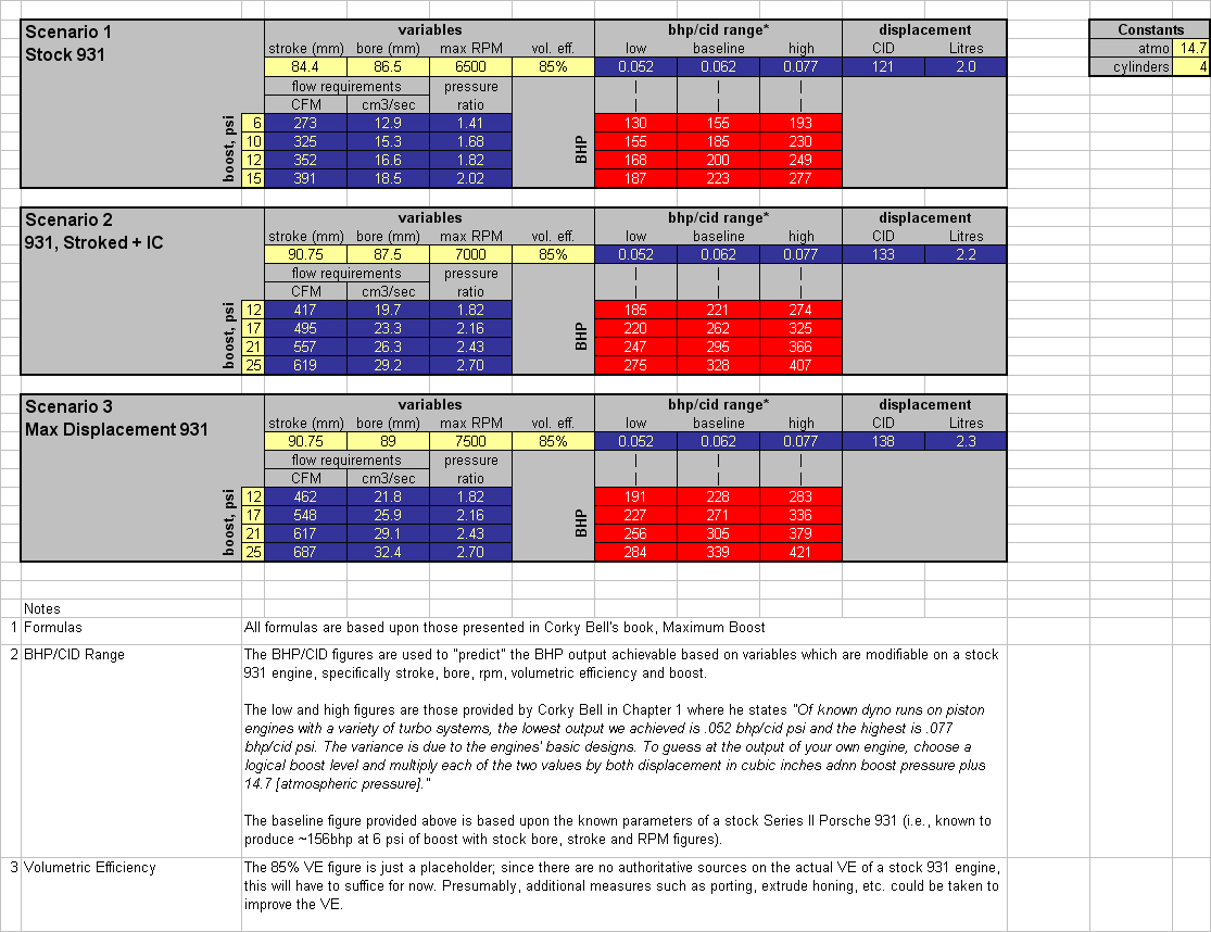
|
Thats exactly what I'm talking about, I guess I explained myself poorly...
_________________
80 Turbo - Slightly Modified |
|
| Back to top |
|
|
|


