| View previous topic :: View next topic |
| Author |
Message |
RC

Joined: 25 Mar 2007
Posts: 2636
Location: Australia
|
 Posted: Tue Mar 10, 2009 4:11 am Post subject: Front Mount Intercooler Install. Posted: Tue Mar 10, 2009 4:11 am Post subject: Front Mount Intercooler Install. |
 |
|
Disclaimer:
In noway whatsoever is there any claim or implication that this is "ultimate" or in fact anything beyond average. There are many possible intercooler options available and as many ways to install them. Although some methods and materials are clearly preferred and offer distinct advantages with specific drawbacks, this is merely the procedure and items I used for this particular job based on available funds, tools, knowledge and skills.
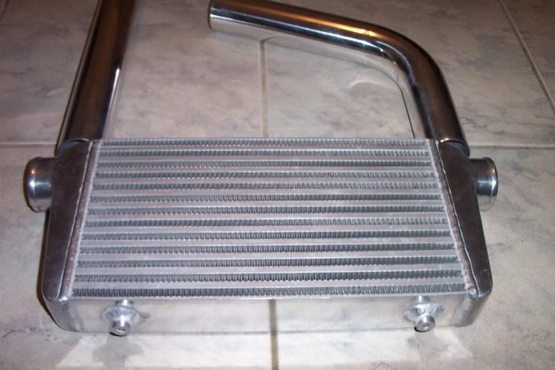
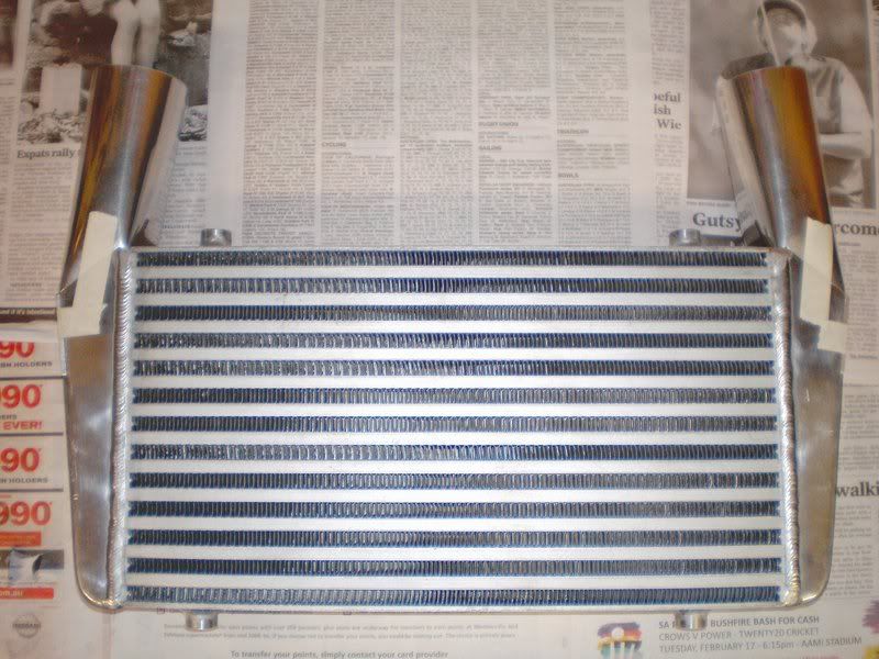
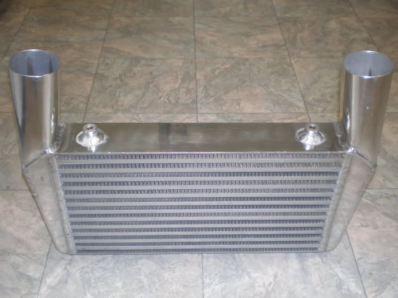
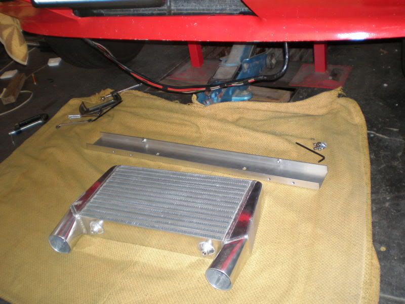
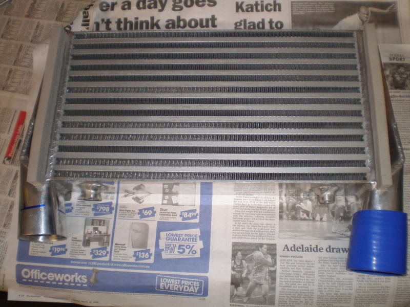
Started with a JDM type aluminium bar and plate cooler from our cheap and often preferred supplier, ebay. Yes, they are made in China. After checking out other more expensive brand name coolers and their packaging in various auto/performance shops, came to the conclusion that they are all made in China. Even the Japanese name ones. Suspect that if they are not all made in the same factory that they use the same components, as evidenced by identical casting flaws on the end tanks.
Have had this cooler sitting around for a while and during that time had thoughts of acquiring and using something different. Then came across this series of tests on various OE and aftermarket coolers that inspired more confidence.
http://autospeed.com/cms/A_1931/article.html
http://autospeed.com/cms/A_1946/article.html
Will try to allow the pictures to do most of the talking now.
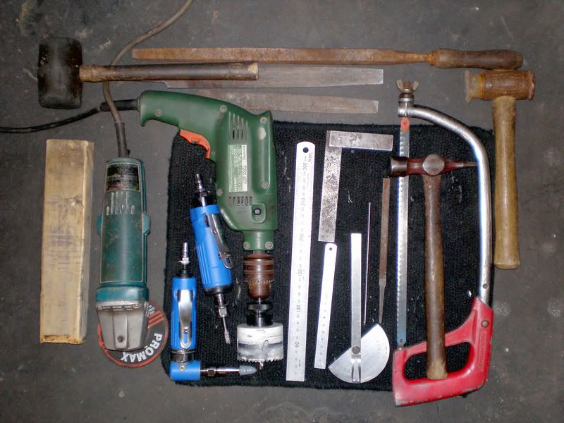
Only basic tools are required. Die grinders are just faster and easier than a drill and/or files. A hole saw can be replaced with a series of small holes and more filing. A jigsaw doesn`t fit and a gas axe is rather crude IMO.
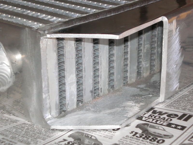
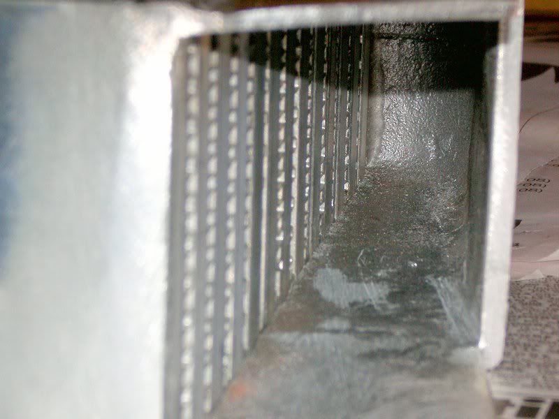
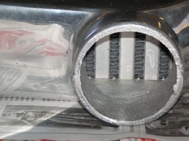
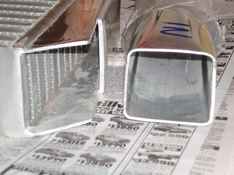
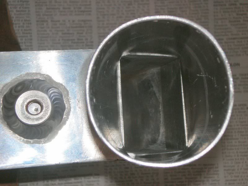
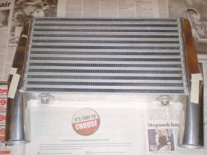
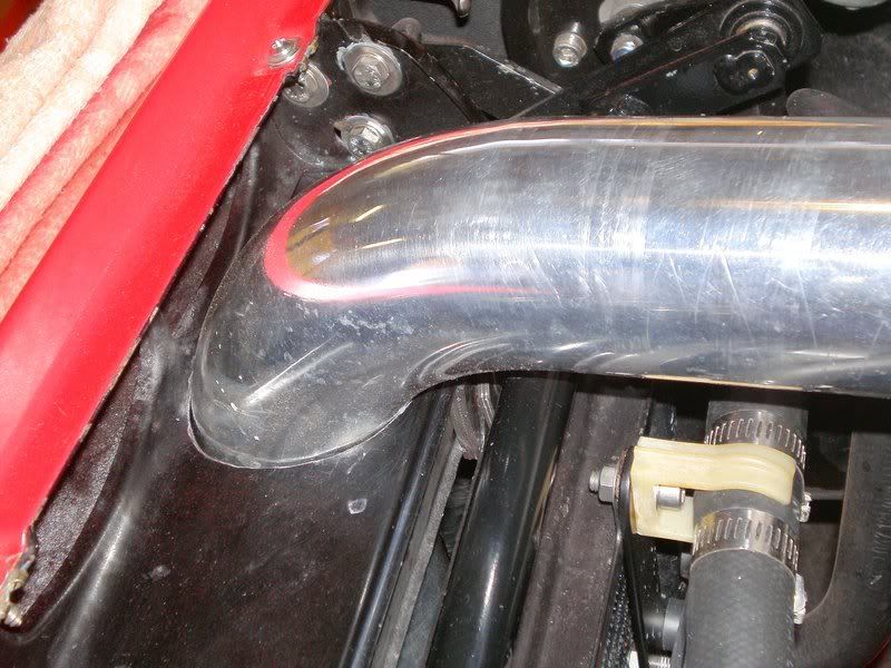
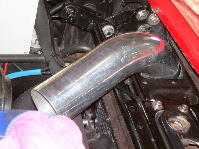
The round piping, or tube really at 2mm wall thickness, was formed into a rectangular transition quite easily using a bit of 60 x 35 pine (or 2 1/2 x 1 1/2 lumber, say oregon, for our US guys) shaped to a slight taper. This was inserted in the tube and driven down while also flattening the edges by hitting with a rubber mallet on the carpet mat. Then the soft face hammer to square the corners more and some light finishing with a smaller size smooth faced hammer.
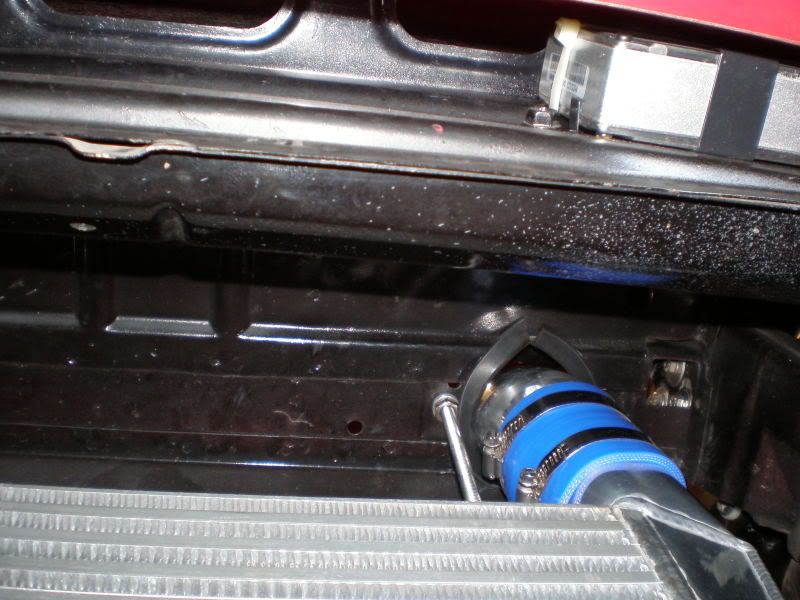
While the intercooler is at the welding shop is a good time to drill some big holes in your Porsche. Decided on running the pipes through the top radiator panel where the depressed section is at each side since this area is reinforced by 2 angle sections spot welded at the front and rear. Only 1 spot was removed in the process and the remaining metal on the outer ends lends support to the panel and the affixed headlight hinge bracket.
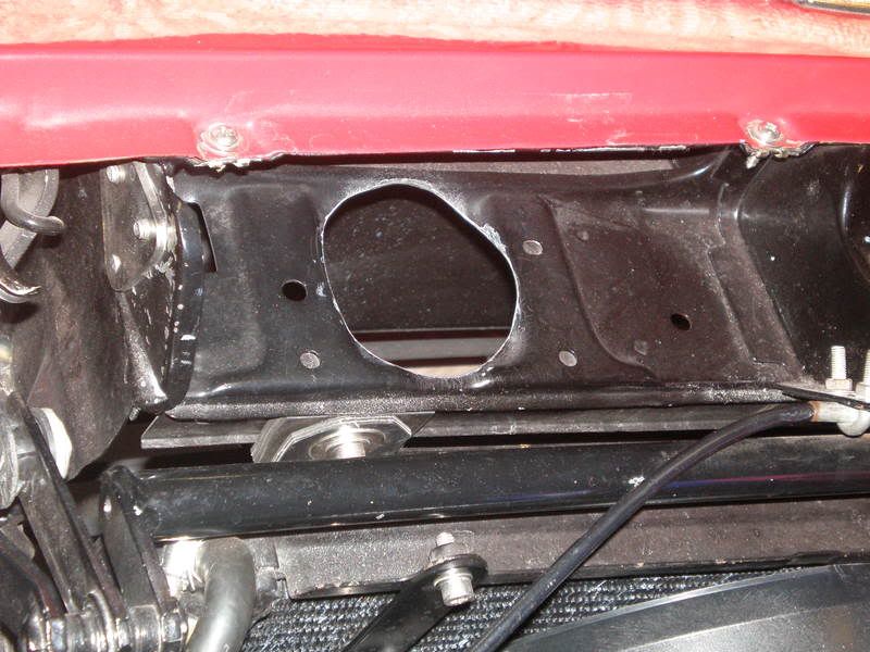
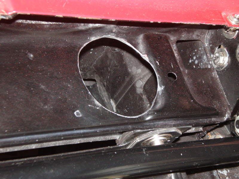
Trial fit is looking good with 2 1/2" pipes in place. Checked that the hood closes too, and appears there`s plenty of clearance by pushing up from underneath.
Well that`s about all I can do to it for a week or so while the aluminium is being welded. Gives me some time to go shopping on ebay for more silicone hose bends. Have a 2 1/4 to 2 1/2 x 90* reducing bend on the SC outlet but need one in 45* now. Cant seem to find one anywhere, or even US and online so appreciate it if someone knows a source. If not will have to weld some 2 1/2" pipe over the 2 1/4 since 2 1/2 x 45 * are no problem. |
|
| Back to top |
|
 |
elitejaso

Joined: 24 Jul 2007
Posts: 138
Location: Melbourne
|
| Posted: Mon Mar 16, 2009 10:33 pm Post subject: |
|
|
Looking good cant wait to see the final setup. Keep those pictures coming.
When our cars are up and running we'll have to go for a run/drive somewhere.
_________________
1981 924 turbo (daily driver) |
|
| Back to top |
|
|
RC
Joined: 25 Mar 2007
Posts: 2636
Location: Australia
|
| Posted: Tue Apr 14, 2009 3:40 am Post subject: |
|
|
Be happy to go for a cruise the length of my driveway ATM. 
Ok, more pics.
Found a welder/fabricator who specializes in intercoolers and performance work.
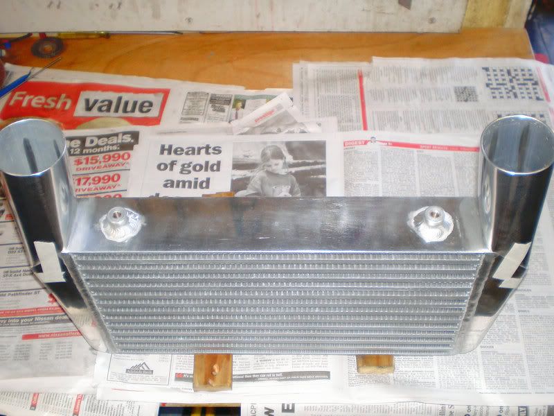
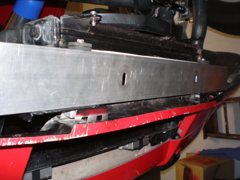
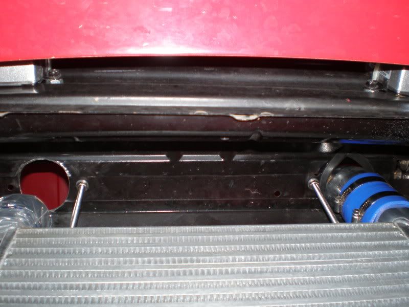
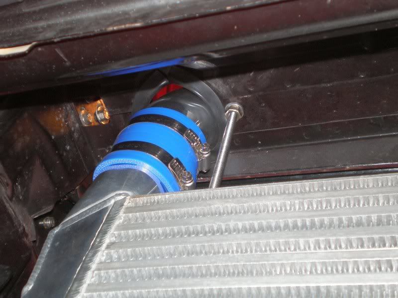
Picked up a length of 3" x 1" aluminium channel to space the radiator back and for the IC bottom mount. Simply drilled holes at the same centres as the radiator and bottom mounts/ front spoiler brackets. Easier to mount radiator by fitting M6 nutserts at the rear. Channel is longer on RHS to allow future mounting of oil cooler.
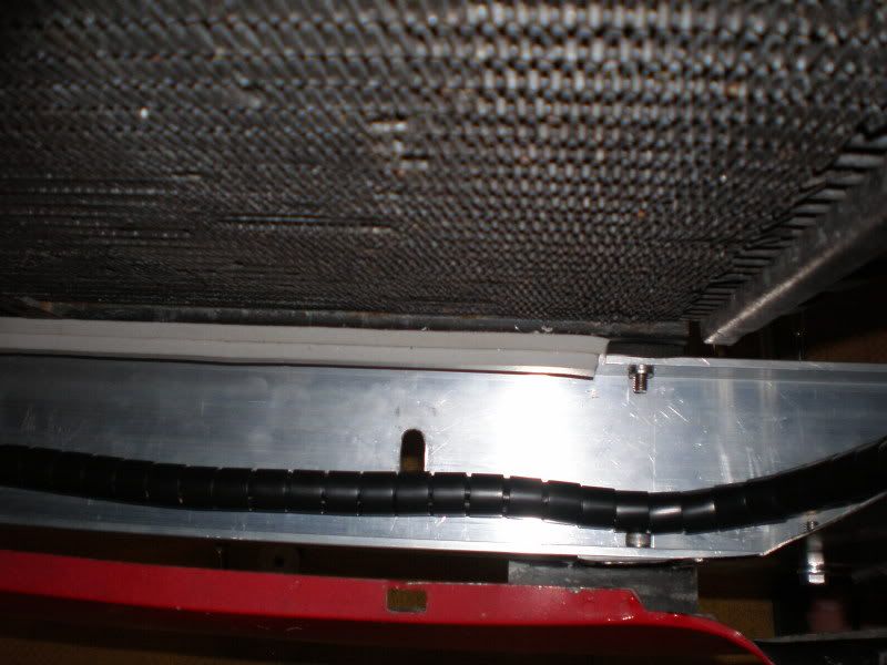
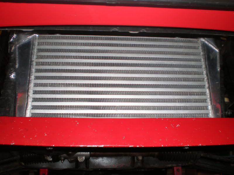
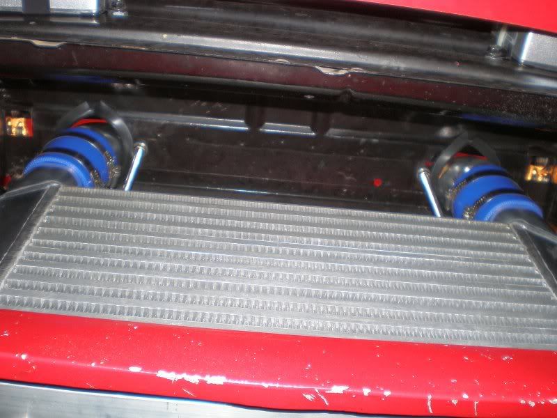
This view is down through the pipe hole showing the protected cabling that runs across the front of our cars. Also a strip of soft rubber at the bottom of the rad to seal against the IC.
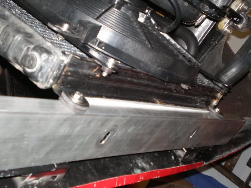
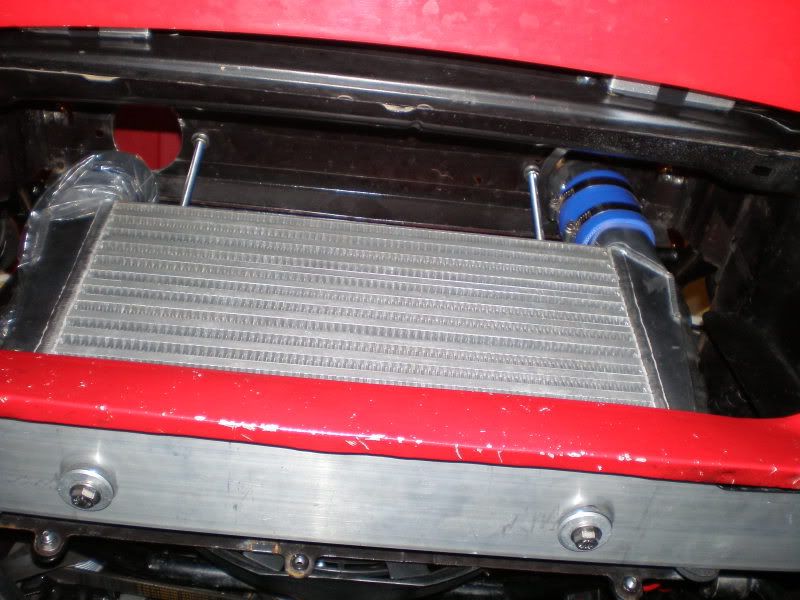
Applied rubber seal at the sides of the IC and a thinner 1/4" x 1 1/2" piece along the upper face. The theory is to provide a seal between the IC and rad while allowing for dispersion between the cores and fins. So all the air entering through the front passes through the IC then the rad. Same principle with the larger aftermarket multiblade fan behind the rad, it is also sealed to the rad core. So when the fan operates it draws cold air in through both cores. In addition to the standard fan switch the fan is also controlled by the ECU and programmed to pre cool the IC while at the lights. Dramatically reducing any heatsoak while stationary and giving me a cold start from the lights should I decide to accelerate quickly, up to the maximum speed limit of course. Perfectly legal! 
Upper mounts are M8 threaded rod (304 S/S) screwed into the IC and fastened in position on the upper panel by a couple of locknuts and washers. Easy.
 |
|
| Back to top |
|
|
ic932
Joined: 11 Feb 2005
Posts: 1104
Location: UK
|
| Posted: Tue Apr 14, 2009 5:39 am Post subject: |
|
|
| Excellent work, a very slick and professional looking installation. |
|
| Back to top |
|
|
Chrenan

Joined: 15 Jan 2003
Posts: 3903
Location: Canada
|
| Posted: Tue Apr 14, 2009 11:05 am Post subject: |
|
|
Very clean work.
_________________
1987 951 - M193 Version for Japan |
|
| Back to top |
|
|
Adismo

Joined: 05 Oct 2008
Posts: 80
Location: Guatemala
|
| Posted: Tue Apr 14, 2009 4:14 pm Post subject: |
|
|
Wow for me i think this is the best solution to put a intercooler for a Porsche 
_________________
Porsche 924 1977 XK Euro |
|
| Back to top |
|
|
RC
Joined: 25 Mar 2007
Posts: 2636
Location: Australia
|
| Posted: Tue May 26, 2009 1:20 am Post subject: |
|
|
Cheers guys.
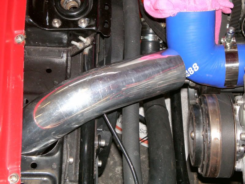
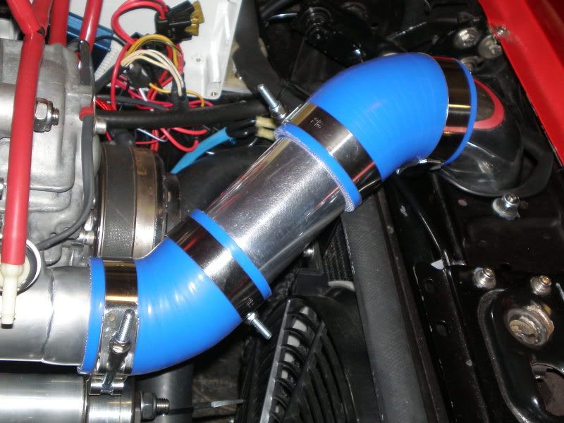
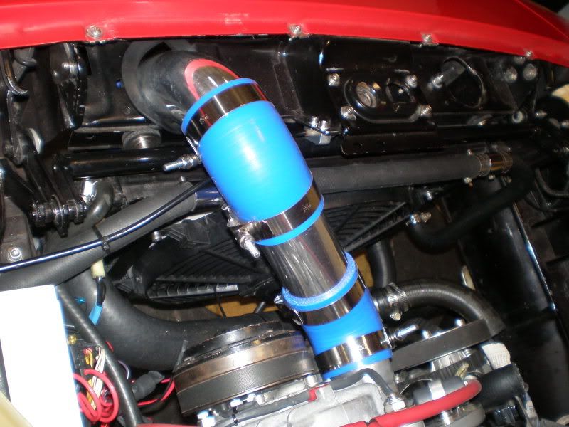
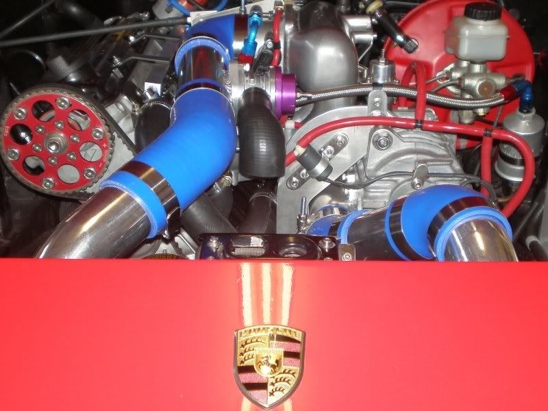
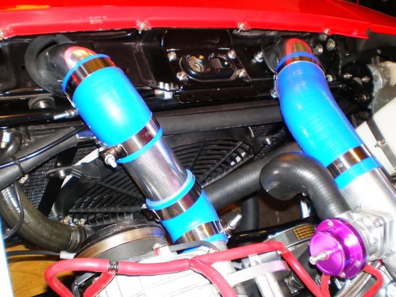
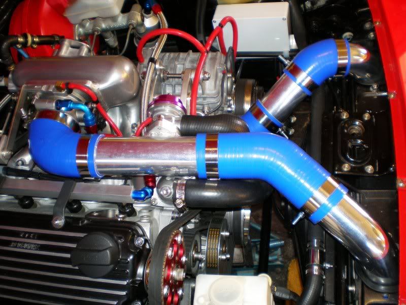
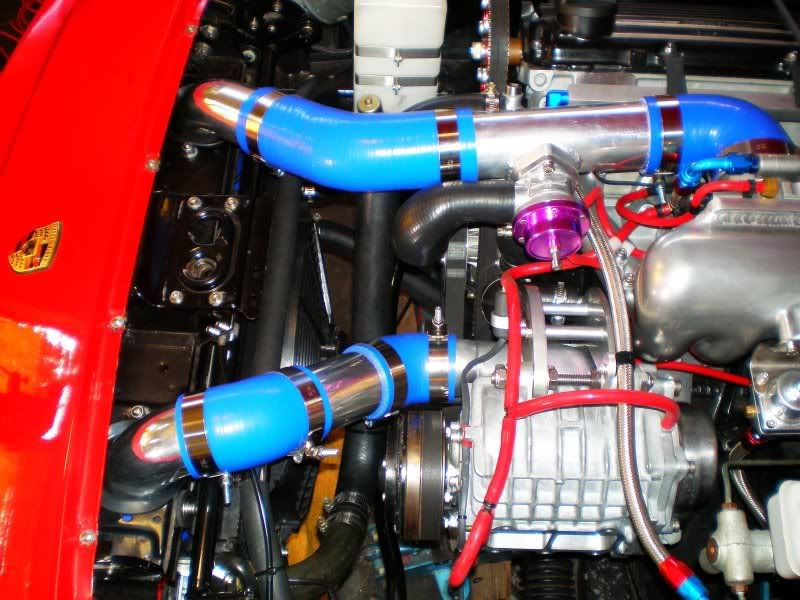
Finally got the plumbing all finished and its up and running. 
More pics, self explanatory.
 |
|
| Back to top |
|
|
RC
Joined: 25 Mar 2007
Posts: 2636
Location: Australia
|
| Posted: Tue May 26, 2009 1:52 am Post subject: |
|
|
So how does it work?
Looks pretty but does it make a difference?
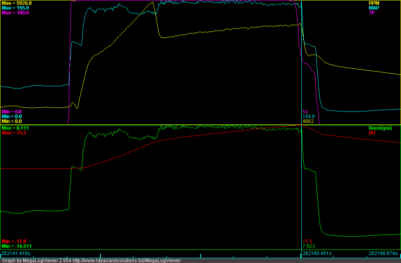
Pics are great eh? Great way to illustrate and saves typing too! Here are some before with no IC datalogs that show the temp rise in degrees C (red trace) under boost (green trace in PSI, both on lower graph). Upper frame has RPM in yellow, throttle position in purple and manifold air pressure, Kpa, light blue. OK, aqua then.
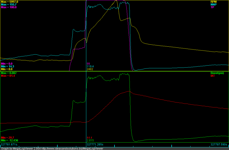
So what`s that? About 23*C.
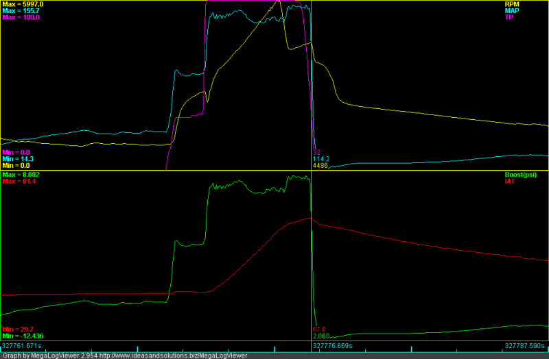
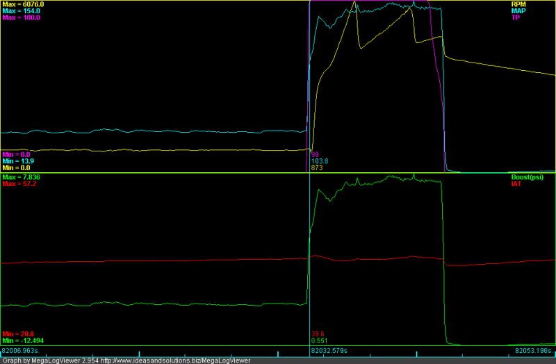
Next pair:
That looks to be 32*C.
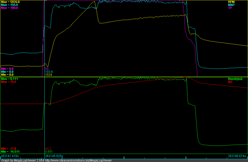
Now for some with the IC fitted:
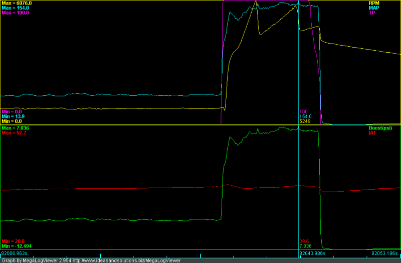
Started at 39* and finished at 39*. Can`t get much better than that?
Look here:
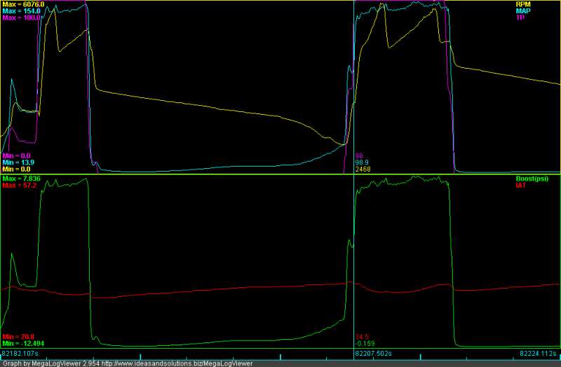
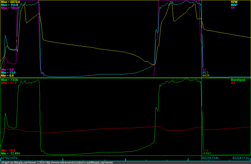
Well, hows that. Finished a boosted run at 1* LESS that it started at. Bloody brilliant or what? Note all runs are from a moving start so the IC is not heatsoaked initially. Works similar to the radiator, faster you go the cooler it gets!
No officer, not speeding, just preventing it overheating. |
|
| Back to top |
|
|
gegge

Joined: 27 Jul 2007
Posts: 1124
Location: Sweden
|
| Posted: Tue May 26, 2009 4:02 am Post subject: |
|
|
Impressive result especially since the IC is relative small and cheap. The Chinese version of the ultimate instal What are the measurements (LxWxH) of the IC?
_________________
Carl Fredrik Torkildsen
924 turbo -81 Carrera GT RESTOMOD
924 turbo -80 Dolomite De Luxe
924 -85 DP kit, BBS RS, M030 and tuned engine
924s -86 Black on black turbo with Fuchs |
|
| Back to top |
|
|
Chrenan
Joined: 15 Jan 2003
Posts: 3903
Location: Canada
|
| Posted: Tue May 26, 2009 4:56 am Post subject: |
|
|
Please re-title this thread "Ultimate" immediately. That is all.
_________________
1987 951 - M193 Version for Japan |
|
| Back to top |
|
|
Rich H
Joined: 10 Jun 2007
Posts: 2665
Location: Preston, Lancs, UK
|
| Posted: Tue May 26, 2009 6:05 am Post subject: |
|
|
I want one. I don't have a Turbo or a Supercharger but I still want an IC like that... Might fit the IC first....
_________________
1994 Lotus Esprit S4 - Work in progress...
1980 Porsche 924 S2 DITC Turbo - Original spec
1978 Homo-Sapiens - Tired spec
1953 Landrover S1 - Pensioner Spec |
|
| Back to top |
|
|
RC
Joined: 25 Mar 2007
Posts: 2636
Location: Australia
|
| Posted: Wed May 27, 2009 1:37 am Post subject: |
|
|
| gegge wrote: | | Impressive result especially since the IC is relative small and cheap. The Chinese version of the ultimate instal What are the measurements (LxWxH) of the IC? |
Yea, I`m very happy it works much better than I expected it to. Cheap alright, Au$80, Chinese ebay bargain. IIRC was around Au$30, paid more for shipping, $50. Am convinced these are same as expensive brand names. Seconds or blems probably, since one bottom mount was welded off centre and one end tank was polished a bit hollow. Mate got similar ebay one that had Greddy stamp half polished off.
The core size is 400 x 230 x 65. Still larger than a 951 IC and more importantly twice the frontal surface area. For equal core volume a larger front area is much more efficient than more depth. Never flowed it but cleaned up (ported) internally at pipes and sure my arrangement offers better flow and more even air distribution through all cores than the original positions. Also eliminates a couple of 90* bends that would not practically fit in the space anyway. Have not recorded any pressure loss at all either.
Chrenan wrote:
| Quote: | | Please re-title this thread "Ultimate" immediately. That is all. |
No, wouldn`t want it to get mistaken for another thread with similar name. Accept it as a compliment though, thanks.
Why would you want one on a NA Rich? Leave the grille off to get more looks from the cops? Intend to anodize it black for camouflage as much as efficiency.
Wouldn`t get the IAT any lower than ambient without a water or nitrous spray. On forced induction or NA trick is to intake coldest air possible. I still have the dodgy cut down cone filter under the hood ATM too. Have modded the SC intake so can be rotated 180*, to face down. Then a 3" silicone hose attaches to a 3" mandrel bend that still needs to be welded to a bit more pipe so I can draw cooler air in from behind the bumper. Would make slight improvement on NA too. Air is denser in the UK anyway. |
|
| Back to top |
|
|
morghen

Joined: 21 Jan 2005
Posts: 8884
Location: Romania
|
| Posted: Wed May 27, 2009 2:23 am Post subject: |
|
|
its not small at all...its actualy a bit bigger than mine..i've calculated mine for a bit over 250HP...yours should be good for slightly more.
edit: this means that its efficiency is around it's maximum until ~250-260HP...after that its efficiency starts to decline...not that at 250 it becomes inneficient.
_________________
https://www.the924.com |
|
| Back to top |
|
|
Rocco R16V

Joined: 03 May 2009
Posts: 497
Location: PNW
|
| Posted: Wed May 27, 2009 3:05 am Post subject: Re: Front Mount Intercooler Install. |
|
|
| RC wrote: | | Well that`s about all I can do to it for a week or so while the aluminium is being welded. Gives me some time to go shopping on ebay for more silicone hose bends. Have a 2 1/4 to 2 1/2 x 90* reducing bend on the SC outlet but need one in 45* now. Cant seem to find one anywhere, or even US and online so appreciate it if someone knows a source. If not will have to weld some 2 1/2" pipe over the 2 1/4 since 2 1/2 x 45 * are no problem. |
Great install, your mods to the intercooler will make it work even better than the original outlet locations.
I know i'm late and it looks as if you got it sorted but for future reference
here is a great site for silicone bends n stuff.
http://www.siliconeintakes.com/index.php?cPath=14&osCsid=d0d36640f496ae3e181346d616ff4817
_________________
"Government exists to protect us from each other. Where government has gone beyond its limits is in deciding to protect us from ourselves. "
Ronald Reagan |
|
| Back to top |
|
|
endwrench

Joined: 07 Dec 2002
Posts: 1631
Location: Victor, Montana
|
| Posted: Sat Jun 06, 2009 4:30 am Post subject: |
|
|
Very nice RC!!! Pretty close to what I did. I used the same IC but I modified it a little different. Your transitions are better than mine and I think you went with 2 1/2" pipe and I did 2 1/4". I was able to keep the stock location on the radiator. I had the same results with virtually 0 deg temp rise. Are you recirculating your blow-off?

By endwrench at 2007-07-28

By endwrench at 2006-05-14
Todd
_________________
'79 924NA. Rebuilt 9.5:1, MSDS header, Mega Squirt Injection, MJLJ-EDIS Ignition, 1.6L Whipple Charger and Intercooler, 10lbs Boost, 944 Trans, Custom HD Clutch.
"simsport" said....superchargers are better than turbos its official!.... |
|
| Back to top |
|
|
|

