| View previous topic :: View next topic |
| Author |
Message |
Finbarr

Joined: 14 Jan 2004
Posts: 85
Location: Worcestershire, UK
|
 Posted: Fri Apr 05, 2013 9:42 pm Post subject: Posted: Fri Apr 05, 2013 9:42 pm Post subject: |
 |
|
| McGyver wrote: | | Actually relay needs only (+12V) signal to be trigged - from coil to input 1 in relay. |
The relay I drew the circuit for (not sure whether yours is the same or not) needs about 50V on pin 1 to trigger it. The 39K and 470R resistors in the bottom left of the diagram reduce this to approximately 0.6V which is what's needed to turn on the transistor and cause a retrigger of the timer IC.
This 50V comes from the back EMF that is generated by the coil when the "points" open. Obviously the standard setup doesn't attempt to limit this voltage to less than 50, but it looks as though driving the coil with the MSD does.
You could modify the relay to require only 12V to trigger it by changing the 39K resistor to less than about 8.9K - something like 7.5K or 6.8K should do.
_________________
1980 931 (with the odd electrical quirk...) |
|
| Back to top |
|
 |
Finbarr
Joined: 14 Jan 2004
Posts: 85
Location: Worcestershire, UK
|
| Posted: Fri Apr 05, 2013 9:55 pm Post subject: |
|
|
| dpw928 wrote: | During cranking the 15 circuit isn't activated. The coil is energized by the 16 circuit which comes off the 50 cranking circuit at the starter. This is for US cars. Not sure on the ROW's.
Dennis |
Circuit 15 should be active during cranking - it's circuit x that isn't. That's the one used for high current items like the headlights and rear window demister that aren't needed in order to start the engine.
_________________
1980 931 (with the odd electrical quirk...) |
|
| Back to top |
|
|
dpw928

Joined: 02 Nov 2002
Posts: 1860
Location: owasso, ok 74055
|
| Posted: Fri Apr 05, 2013 10:19 pm Post subject: |
|
|
| Finbarr wrote: | | dpw928 wrote: | During cranking the 15 circuit isn't activated. The coil is energized by the 16 circuit which comes off the 50 cranking circuit at the starter. This is for US cars. Not sure on the ROW's.
Dennis |
Circuit 15 should be active during cranking - it's circuit x that isn't. That's the one used for high current items like the headlights and rear window demister that aren't needed in order to start the engine. |
That may be the case on UK vehicles but on US vehicles the 16 circuit powers the coil during cranking.
Dennis
_________________
81 931 5 sp
78 928 5 sp Silver
78 928 AT Euro Black |
|
| Back to top |
|
|
5yearplan
Joined: 14 Feb 2013
Posts: 7
Location: Michigan
|
| Posted: Fri Apr 05, 2013 10:31 pm Post subject: |
|
|
| Yes I understand, I have MSD ignition control, not msd coil, the msd ecu doesnt need the starter activation to coil during cranking... Right now I'm trying to figure out what tells the ECU to power the fuel pump relay, whether its using the impulse sender from the dizzy in order to shut the relay off if theres no rpm |
|
| Back to top |
|
|
Finbarr
Joined: 14 Jan 2004
Posts: 85
Location: Worcestershire, UK
|
| Posted: Fri Apr 05, 2013 11:15 pm Post subject: |
|
|
| dpw928 wrote: | | Finbarr wrote: | | Circuit 15 should be active during cranking - it's circuit x that isn't. That's the one used for high current items like the headlights and rear window demister that aren't needed in order to start the engine. |
That may be the case on UK vehicles but on US vehicles the 16 circuit powers the coil during cranking.
Dennis |
I don't see any difference between the UK and US circuit diagrams or in the part numbers for the ignition switch, so although you may be right I'm baffled as to how (or why) circuit 15 would be disconnected from the coil during cranking on US models only.
My understanding has always been that the purpose of circuit 16 was to provide extra voltage to the coil during cranking, when the battery voltage is reduced by the load from the starter, and not to replace the normal supply through circuit 15. The models that use circuit 16 have a resistance wire of 1R to the coil from circuit 15 and 1.5R from circuit 16, which would result in lower coil voltage during cranking unless circuit 15 stayed active.
_________________
1980 931 (with the odd electrical quirk...) |
|
| Back to top |
|
|
dpw928
Joined: 02 Nov 2002
Posts: 1860
Location: owasso, ok 74055
|
| Posted: Sat Apr 06, 2013 12:04 am Post subject: |
|
|
I don't have my electrical schmatics here at work, but IIRC only the 50 circuit is enegized at the ignition switch during cranking. I do know from experience that if the 16 circuit resistor or resistor wire is bad, there is no voltage applied to the coil on US cars (part of safety feature?), i.e. no start during cranking as the original OP is seeing. On UK cars, it should be easy enough to check with a volt meter at the coil.
5yearplan,
If you want the pump to work during cranking, run a jumper from the 16 circuit to the 15 connector on the relay. Actually, if your accumulators and pump check valve are good, the fuel system should have enough pressure to start the engine.
Dennis
_________________
81 931 5 sp
78 928 5 sp Silver
78 928 AT Euro Black |
|
| Back to top |
|
|
5yearplan
Joined: 14 Feb 2013
Posts: 7
Location: Michigan
|
| Posted: Sat Apr 06, 2013 3:23 am Post subject: |
|
|
| Finbarr wrote: | | McGyver wrote: | | Actually relay needs only (+12V) signal to be trigged - from coil to input 1 in relay. |
The relay I drew the circuit for (not sure whether yours is the same or not) needs about 50V on pin 1 to trigger it. The 39K and 470R resistors in the bottom left of the diagram reduce this to approximately 0.6V which is what's needed to turn on the transistor and cause a retrigger of the timer IC.
This 50V comes from the back EMF that is generated by the coil when the "points" open. Obviously the standard setup doesn't attempt to limit this voltage to less than 50, but it looks as though driving the coil with the MSD does.
You could modify the relay to require only 12V to trigger it by changing the 39K resistor to less than about 8.9K - something like 7.5K or 6.8K should do. |
Yes part # and circuit inside relay are the same...Ok now we're getting to my problem; with the stock components refitted I am not seeing 50V from coil to FP relay, instead I have 1.5v key on, 3.3v while cranking but I do have 12v at the 87 pin to fuel pump 
| Quote: |
5yearplan,
If you want the pump to work during cranking, run a jumper from the 16 circuit to the 15 connector on the relay. Actually, if your accumulators and pump check valve are good, the fuel system should have enough pressure to start the engine. |
I was having the issue of the car not starting while cranking due to starter wire not hooked up to coil, I believe I have resolved this, it seems I am not getting the 50v signal to the FP relay pin 1 from the stock components or with the MSD installed |
|
| Back to top |
|
|
5yearplan
Joined: 14 Feb 2013
Posts: 7
Location: Michigan
|
| Posted: Mon Apr 08, 2013 11:07 pm Post subject: |
|
|
I was able to scope the signal with the msd installed and stock ECU piggybacked so I could see the signal with the car actually running, and it looks like pin 1 does receive 50 volts! So it looks like I need to build my own circuit  |
|
| Back to top |
|
|
5yearplan
Joined: 14 Feb 2013
Posts: 7
Location: Michigan
|
| Posted: Tue Apr 09, 2013 5:36 am Post subject: |
|
|
| Quote: | The relay I drew the circuit for (not sure whether yours is the same or not) needs about 50V on pin 1 to trigger it. The 39K and 470R resistors in the bottom left of the diagram reduce this to approximately 0.6V which is what's needed to turn on the transistor and cause a retrigger of the timer IC.
This 50V comes from the back EMF that is generated by the coil when the "points" open. Obviously the standard setup doesn't attempt to limit this voltage to less than 50, but it looks as though driving the coil with the MSD does.
You could modify the relay to require only 12V to trigger it by changing the 39K resistor to less than about 8.9K - something like 7.5K or 6.8K should do. |
Removed the 470k resistor and put in a 4.7k and the relay stays energized with the tach out signal from the MSD. thanks for the help  |
|
| Back to top |
|
|
McGyver

Joined: 24 Feb 2009
Posts: 354
Location: Jelenia Gora - Poland
|
| Posted: Fri Apr 26, 2013 10:16 am Post subject: |
|
|
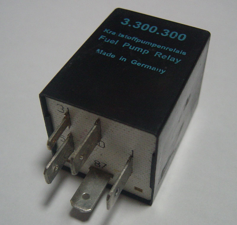
I compared KAE and original 3.300.300 and there's some differences. Especially that KAE doesn't give power for fuel pumps - that function wasn't implemented in it at all... only by adding few elements is possible to get it work as original. KAE works only when engine is turning... and that's all it can do!
Original 3.300.300 works as it should so it gives approx 3seconds power for fuel pumps after key was turned... and starts to work continuously when engine turns.
I try to make scheme for it when I find some free time to do this
I compare relay like that with KAE replacement (same 3.300.300 s/n)
And KAE:

_________________
931 82' - 5000km after full engine rebuild
SOLD: 924 81' N/A- with turbo gearbox "dogleg" - great but mysterious car 
www.mauser98k.internetdsl.pl - if someone like german rifles (English version avalible) |
|
| Back to top |
|
|
72rallye
Joined: 08 Apr 2023
Posts: 16
Location: San Diego, CA, USA
|
| Posted: Tue Oct 31, 2023 9:34 am Post subject: 931.615.113.00 circuit diagram |
|
|
Reviving a 10+ year old thread.
I have two of the 931.615.113.00 fuel pump relays. One was working, the other one wasn't. In order to repair it I traced the circuit diagram. That's a tedious job and in the end I didn't even need it. One wire inside was broken, apparently from vibration.
Having the diagram, though, is nice for future repairs and makes it possible to modify the circuit. There are two time constants of interest:
- The relay has a rev-limiter built-in. Above a certain rpm it shuts off the fuel pump(s). This limit is adjustable via a potentiometer inside. The factory setting is 6000rpm and the full adjustment range is about 5400-6600rpm. A wider range is possible by changing one resistor.
- The relay initially runs the fuel pump(s) for 1 second and then keeps it running only if it sees triggers from the ignition coil. It may be of interest to extend the initial turn-on phase to several seconds to make engine start-up easier. This can be accomplished by changing one resistor and/or capacitor.
Unfortunately, I don't have a way to post images. If someone wants to post the circuit, shoot me a PM and I'll email you the drawing.
Thomas
Edit: The 555 issues a 5.0ms pulse, which should correspond to a 6000rpm rev-limit. However, the actually measured limit is 6400rpm. I don't know why that is. The discrepancy is not due to a faulty tach, because the rpms were measured with a scope. The available adjustment range should then be 5800-7000rpm.
_________________
81 931 currently being resurrected after a 22yr hiatus
86 951, 86 928 5spd, 75 911S coupe |
|
| Back to top |
|
|
72rallye
Joined: 08 Apr 2023
Posts: 16
Location: San Diego, CA, USA
|
|
| Back to top |
|
|
gord
Joined: 08 Feb 2022
Posts: 6
Location: Toronto, Ontario
|
| Posted: Sat Feb 03, 2024 2:29 pm Post subject: 931 Fuel Pump Relay schematic diagram |
|
|
Here is the 931 fuel pump relay schematic diagram, courtesy of @72rallye:

Gord |
|
| Back to top |
|
|
|

